7.EtherNet/IP Connection Procedure
7.2. Balluff Network Module Setup
Set up the Balluff Network Module.
7.2.1. Hardware Settings
Connect the cables and the Proximity Sensor to the Network Module.
Precautions for Correct Use
Make sure that the power supplies are OFF when you set up.
If any of them are ON, the settings described in the following steps and subsequent
procedures may not be applicable.
1
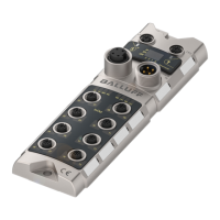
Make sure that Module /
sensor, Actuator and Switching
hub power supplies are all
OFF.
Check the positions of the
ports, keys and LED on
Network Module by referring to
the figure on the right.
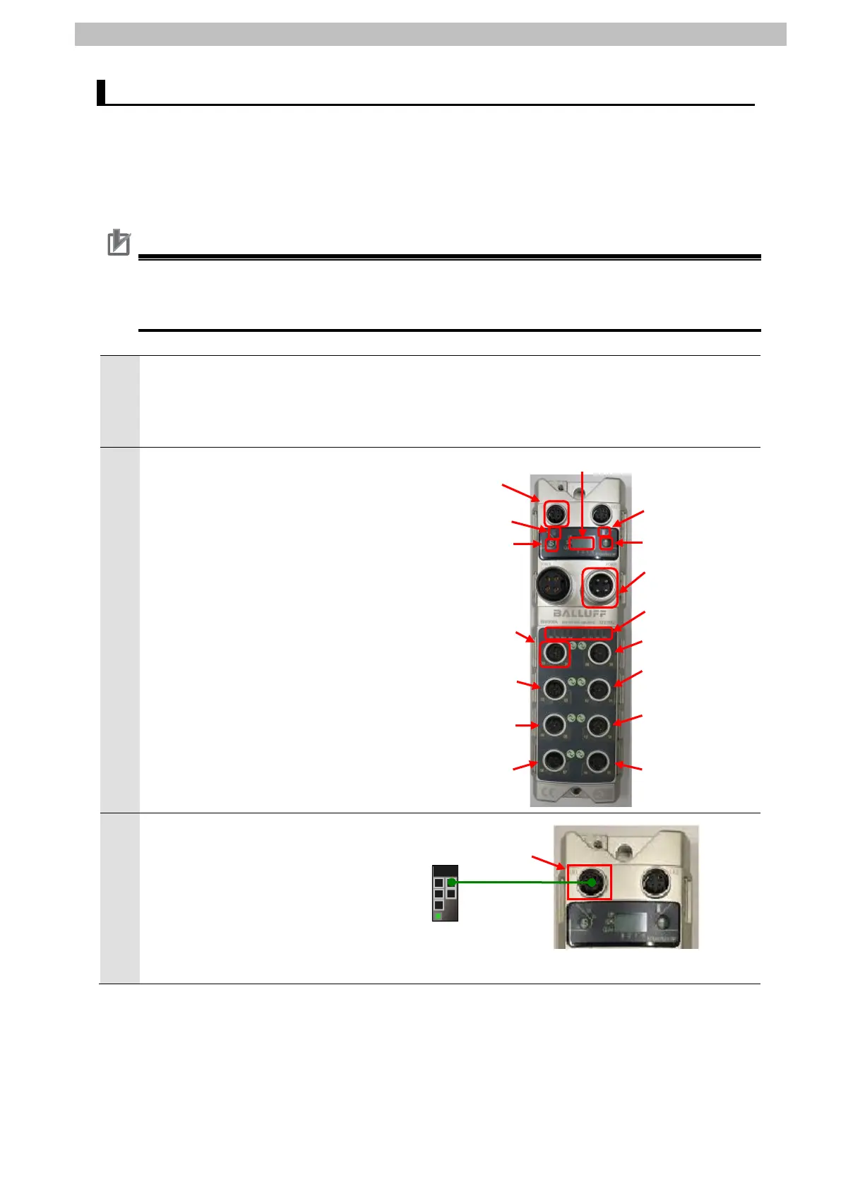
3
Connect Switching hub and
EtherNet/IP
TM
port 1 on
Network Module with an
Industrial Ethernet cable.
Industrial
Ethernet
cable
 Loading...


