EasyManuals Logo

Balluff BNI EIP-50 105-Z015 Series User Manual

Balluff BNI EIP-50 105-Z015 Series
64 pages
To Next Page IconTo Next Page
To Previous Page IconTo Previous Page
Page #22 background imageLoading...
Page #22 background image
7EtherNet/IP Connection Procedure
19
4
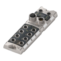
Connect Proximity Sensor to
Port 0 on Network Module.
5
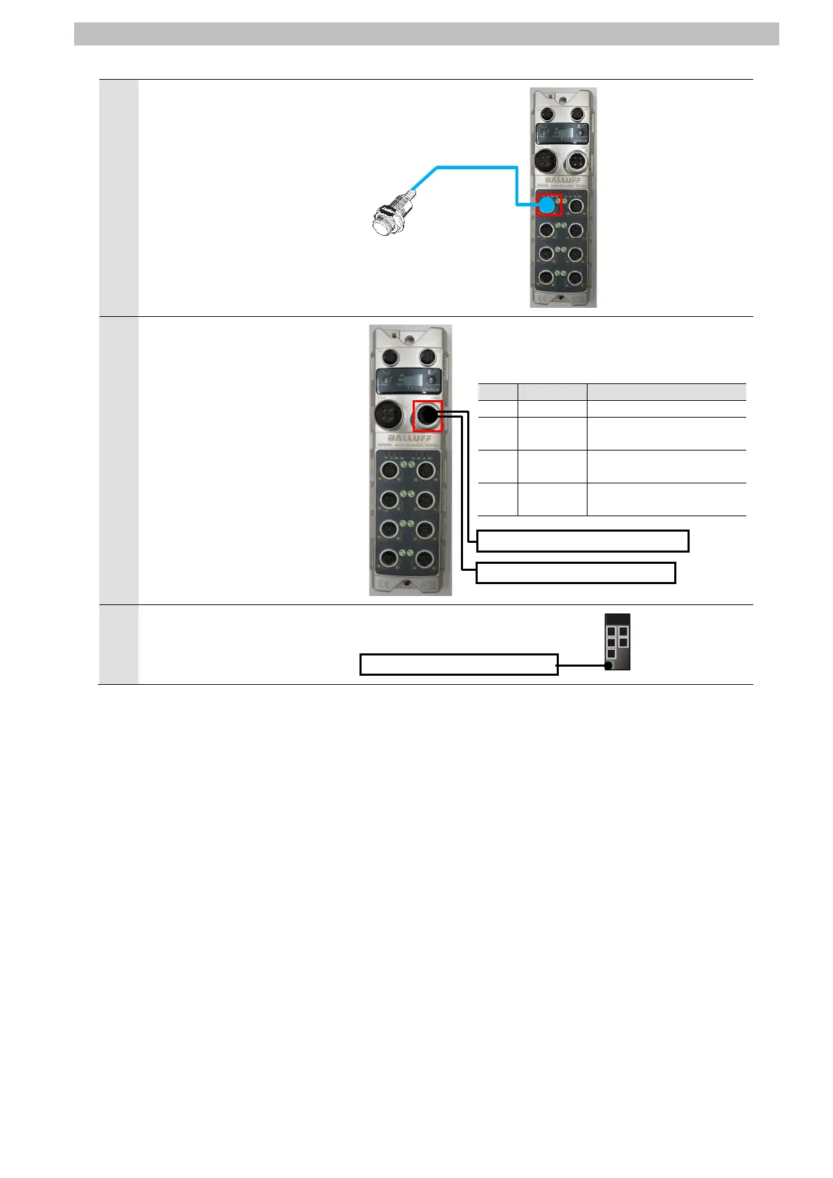
Connect Module / sensor
power supply and Actuator
power supply to Power supply
input port on Network Module.
*For connecting the power
supplies to Network Module,
refer to 3.3. Electrical
connection of the BNI
EIP-508-105-Z015 IP67
Modules 8 IO-Link/In-/
Outputs, 8 In-/Outputs User's
Guide (893539).
Power supply input port pin assignment
Pin
Function
Description
1
+24V
Actuator power supply
2
+24V
Module / sensor power
supply
3
0V
GND module / sensor
power supply
4
0V
GND actuator power
supply
6
Connect Switching hub power
supply to Switching hub.
Module / sensor power supply
Actuator power supply
Switching hub power supply

Questions and Answers:

Question and Answer IconNeed help?

Do you have a question about the Balluff BNI EIP-50 105-Z015 Series and is the answer not in the manual?

Balluff BNI EIP-50 105-Z015 Series Specifications

General IconGeneral
BrandBalluff
ModelBNI EIP-50 105-Z015 Series
CategoryControl Unit
LanguageEnglish

Related product manuals