8 english
4.1 Installation guidelines
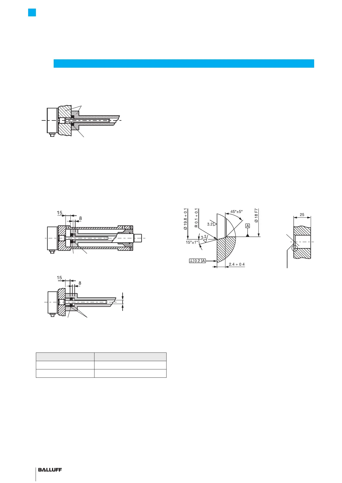
Non-magnetizable material
Magnet
Non-magnetizable material
1)
Min. ØD2= Minimum diameter of the bore (seeTab. 4-1)
Fig. 4-1: Installation in non-magnetizable material
Magnetizable material
If using magnetizable material, the transducer must be
protected against magnetic interference through suitable
measures (e.g. spacer ring made of non-magnetizable
material, a suitable distance from strong external magnetic
fields).
Spacer ring made of non-magnetizable
material
Magnet
min. Ø D2
1)
Spacer ring made of non-magnetizable
material
Magnet
1)
Min.ØD2=Minimum diameter of the bore (seeTab. 4-1)
Fig. 4-2: Installation in magnetizable material
Tube diameter Bore diameter D2
10.2mm At least 13mm
8mm At least 11mm
Tab. 4-1: Bore diameter if installed in a hydraulic cylinder
4.2 Preparing for installation
Installation note: We recommend using non-
magnetizable material to mount the transducer and
magnet.
Horizontal assembly: For horizontal assembly with
nominal lengths > 500 mm, support the rod and tighten it
at the end if necessary (only possible with a diameter of
10.2mm).
Hydraulic cylinder: If installed in a hydraulic cylinder,
ensure that the minimum value for the bore diameter of the
support piston is complied with (seeTab. 4-1).
Fitting bore: The mounting surface of the transducer
housing must make full contact with the supporting
surface. A suitable O-ring must completely seal the bore,
i.e. the countersink for the O-ring must be produced in
accordance with Fig. 4-3.
Fig. 4-3: Fitting bore for installing the BTL with O-ring
Magnet: Various magnets are available for the BTL7
transducer (See Accessories on page22).
4
Installation and connection
Fitting bore
Countersink for
O-ring 15.4×2.1
BTL7-A/C/E/G5 __ -M ____ -K(8)-SR32/SR115/___
Micropulse Transducer - Rod Style

 Loading...


