www.balluff.com 7english
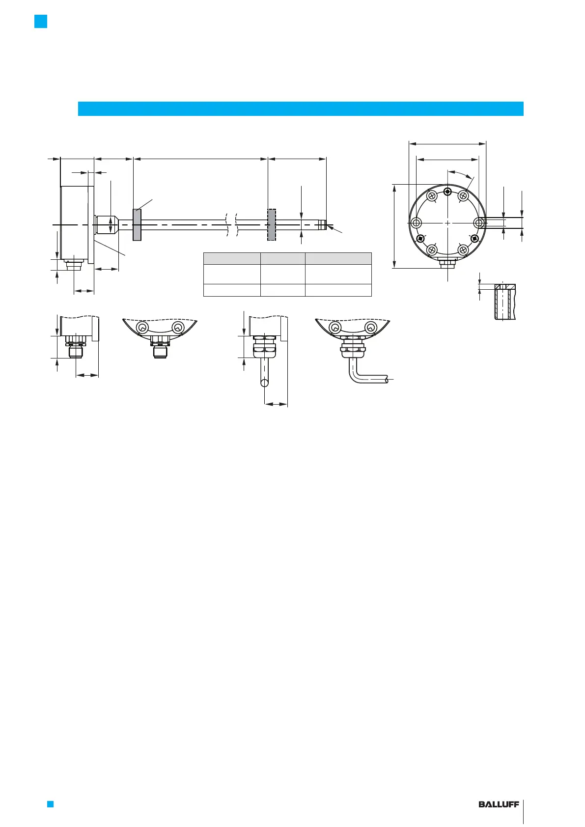
Fig. 3-1:
30°
34 40-1
6
Ø D1
Ø 18 h6
60
25
20.5
G
Ø 64
Ø 6.4
Ø 11
86
20.5
20.5
~18
6
Version D1 G
…-K-… 10.2 mm Thread
M4x4/6deep
…-K8-… 8 mm No thread
BTL7-…-K(8)-… transducer, construction and function
3.1 Construction
Electrical connection: The electrical connection is made
via a cable or a connector (see Type code breakdown on
page25).
Housing: Housing containing the processing electronics.
Fastening: For secure fastening, tighten the transducer
with cylinder screws (ISO4762, M6×16-A2-70) at all
6mounting holes (see Fig. 3-1). All screws must be
tightened with 3.5Nm.
The transducers with Ø 10.2 mm have an additional thread
at the end of the rod to support larger nominal lengths.
Magnet: Defines the position to be measured on the
waveguide. Magnets are available in various models and
must be ordered separately (see Accessories on
page22).
Nominal length: Defines the available measuring range.
Rods with various nominal lengths from 25 mm to
7620mm are available depending on the version:
– Ø10.2mm: Nominal length from 25mm to 7620mm
– Ø8mm: Nominal length from 25mm to 1016mm
Damping zone: Area at the end of the rod that cannot be
used for measurements, but which may be passed over.
3.2 Function
The Micropulse Transducer contains the waveguide which
is protected by an outer stainless steel tube (rod). A
magnet is moved along the waveguide. This magnet is
connected to the system part whose position is to be
determined.
The magnet defines the position to be measured on the
waveguide.
An internally generated INIT pulse interacts with the
magnetic field of the magnet to generate a torsional wave
in the waveguide which propagates at ultrasonic speed.
The component of the torsional wave which arrives at the
end of the waveguide is absorbed in the damping zone to
prevent reflection. The component of the torsional wave
which arrives at the beginning of the waveguide is
converted by a coil into an electrical signal. The travel time
of the wave is used to calculate the position. Depending
on the version, this information is made available as a
voltage or current output with a rising or falling gradient.
3
Construction and function
BTL7…-SR32
BTL7…-SR115 BTL7… cable
Mounting
surface
1)
Unusable area
2)
Not included in scope of delivery
Damping zone
Magnet
1)
Nominal length =
Measuring range
2)
1)
6 holes to fasten
the transducer
BTL7-A/C/E/G5 __ -M ____ -K(8)-SR32/SR115/___
Micropulse Transducer - Rod Style

 Loading...


