www.balluff.com 7english
3
Construction and function (continued)
3.3 LED display
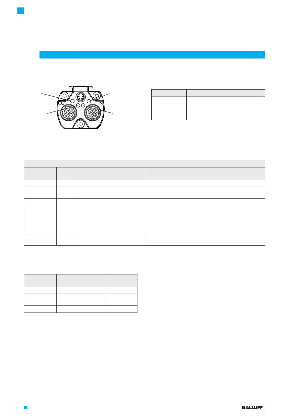
Fig. 3-2: BTL7 LED displays
3.3.1 LED 1: BTL status
LED1 Operating state
Green Normal function
Magnet is within the limits.
Red Error
No magnet or magnet outside the limits.
Tab. 3-1: LED1
LED2
(PROFINET
status)
LED1
(BTL status)
LED3
(Link/Activity
IN)
LED4
(Link/Activity
OUT)
3.3.2 LED2: PROFINET status (dual LED)
LED2
Red
(Bus Failure)
Green Meaning Cause
Off Off No supply voltage
On On No bus connection with other
participants (no link)
Bus not connected
Master cannot be accessed or is switched off
Flashing
1)
On Bus connection (link) available, but
the sensor is not involved in cyclic
data exchange.
Sensor is starting up, but parameterization has not yet been
completed.
Sensor has been incorrectly configured.
The sensor was assigned an incorrect station address and is thus
not accessible.
The desired configuration is not the same as the sensor
configuration.
Off On The sensor is involved in cyclic data
exchange.
1)
Flashing frequency is 0.5Hz. The signal is shown for at least 3s.
Tab. 3-2: LED2
3.3.3 LED3/LED4: Link/Activity
LED3/LED4
Green
Status Connection
On Port open Yes
Flashing Requested by the master
to identify the device
Yes
Off Port closed No
Tab. 3-3: LED3/4
BTL7-V50T-M ____ -P-C003
Micropulse Transducer in a Profile Housing

 Loading...


