8 english
4.1 Installing the transducer
NOTICE!
Improper installation
Improper installation can compromise the function of the
transducer and result in damage.
► For this reason, ensure that no strong electrical or
magnetic fields are present in the immediate vicinity
of the transducer.
► The recommended spacing for the installation must
be strictly observed.
Any orientation is permitted. Mount the transducer on a
level surface of the machine using the provided mounting
clamps and cylinder-head screws. A sufficient number of
mounting clamps is supplied.
In order to avoid the development of resonant
frequencies from vibration loads, we
recommend arranging the mounting clamps at
irregular intervals.
The transducer is electrically isolated from the machine
with the supplied insulating bushes (see Figure 3-1).
1. Guide the transducer into the mounting clamps.
2. Attach transducer to the base using mounting screws
(tighten screws in the clamps with max.2Nm).
3. Insert magnet (accessories).
The micropulse transducer in profile housing is
suitable both for floating, i.e. non-contacting
magnets (see Figures4-5 to4-9) and for captive
magnets (see Figures4-2 to 4-4).
The distance (L) between the magnets must be at least
65mm.
Fig. 4-1:
L L L
Distance between the magnets
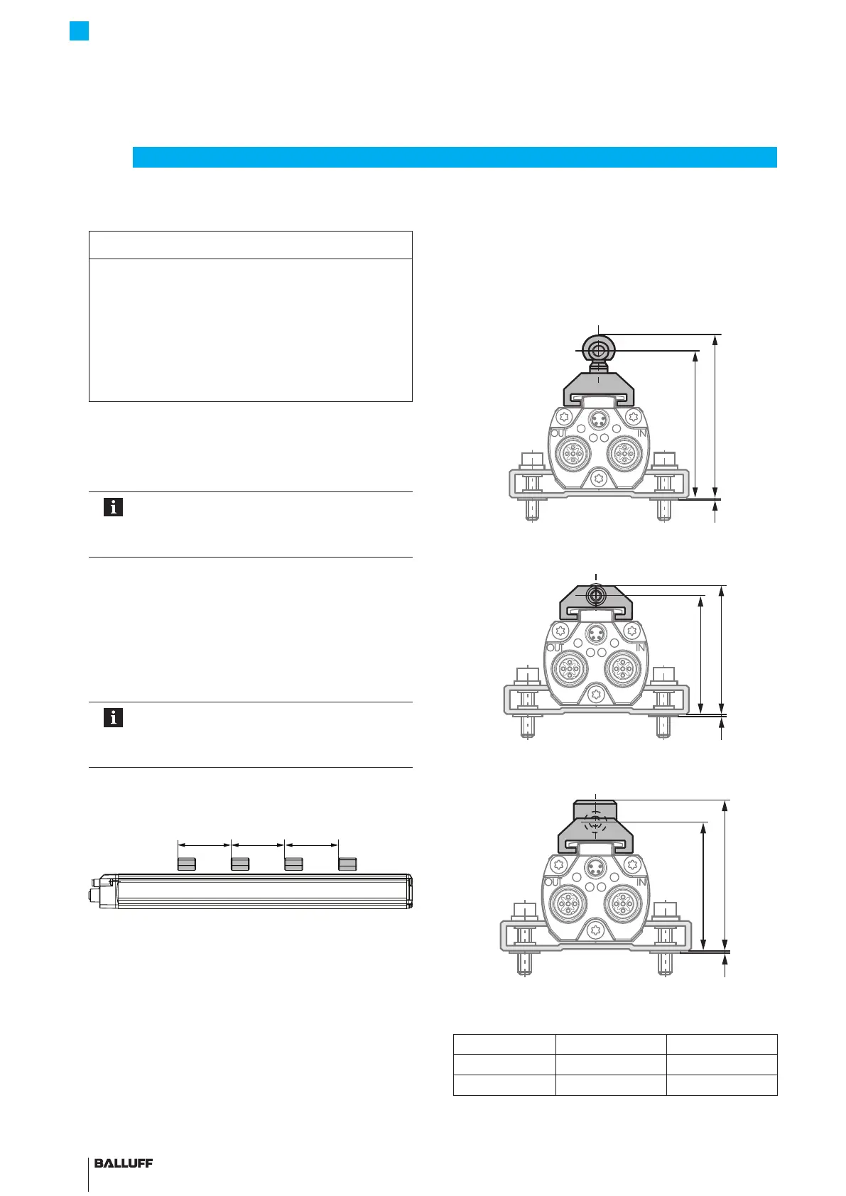
4.2 Captive magnets
The following must be observed when installing the
magnet:
– Avoid lateral forces.
– Connect the magnet to the machine member with a
joint rod (see Accessories on page13).
Fig. 4-2:
66.4
60
1
Dimensions and distances with BTL5-F-2814-1S magnet
Fig. 4-3:
52.5
47.5
1
Dimensions and distances with BTL5-T-2814-1S magnet
Fig. 4-4:
Y
X
1
Dimensions and distances with BTL5-M/N-2814-1S
magnet
BTL5-M-2814-1S BTL5-N-2814-1S
Distance X 48.5mm 57mm
Distance Y 51mm 59.5mm
Tab. 4-1: Distances with BTL5-M/N-2814-1S magnet
4
Installation and connection
BTL7-V50T-M ____ -P-C003
Micropulse Transducer in a Profile Housing

 Loading...


