www.balluff.com 9english
4
Installation and connection (continued)
4.3 Floating magnets
The following must be observed when installing the
magnet:
– To ensure the accuracy of the position measuring
system, the magnet is attached to the moving member
of the machine using non-magnetizable screws
(stainless steel, brass, aluminum).
– The moving member must guide the magnet on a track
parallel to the transducer.
– Ensure that the distance A between parts made of
magnetizable material and the magnet is at least
10mm (see Figures4-5 to4-9).
– Maintain the following values for distance B between
the magnet and transducer and for center offsetC (see
Figures4-5 to4-9):
Type of magnet DistanceB
1)
OffsetC
BTL5-P-3800-2 0.1 to 4mm ±2mm
BTL5-P-5500-2 5 to 15mm ±15mm
BTL5-P-4500-1 0.1 to 2mm ±2mm
BTL6-A-3800-2 4 to 8mm
2)
±2mm
BTL6-A-3801-2 4 to 8mm
2)
±2mm
1)
The selected distance should stay constant over the entire measuring
length.
2)
For optimum measurement results, a distanceB of 6 to 8 mm is
recommended.
Tab. 4-2: Distance and offset for floating magnets
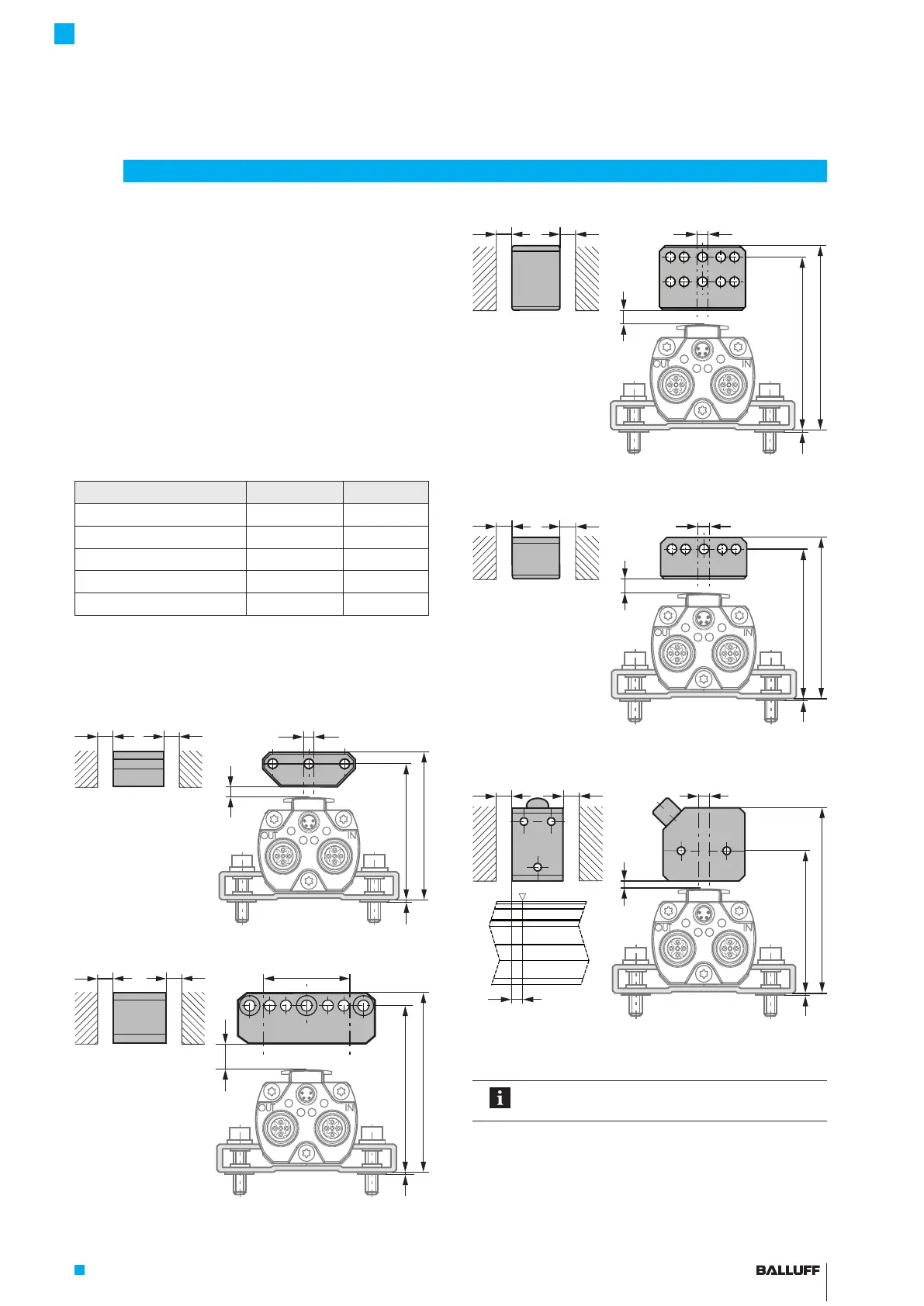
Fig. 4-5:
B
50+4
A
A
55+4
1
Dimensions and distances with BTL5-P-3800-2 magnet
Fig. 4-6:
B
1
61+10
66+10
Dimensions and distances with BTL5-P-5500-2 magnet
Fig. 4-7:
B
A
A
1
74+4
69+4
Dimensions and distances with BTL6-A-3800-2 magnet
Fig. 4-8:
B
A
A
1
63+4
58+4
Dimensions and distances with BTL6-A-3801-2 magnet
Fig. 4-9:
B
A
A
4
1
81+2
57.5+2
Dimensions and distances with BTL5-P-4500-1
electromagnet (24V/100mA)
The measuring range is offset by 4mm towards
the BTL plug (see Figure 4-9).
Plug with
LED
BTL7-V50T-M ____ -P-C003
Micropulse Transducer in a Profile Housing

 Loading...


