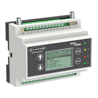
3 DXM Connections
3.1 I/O Base Board Connections
ON
ON
1
1
1
1
1
1
1
1
LED2
C95
TB1
C6
R121
FET9
R82
TB4
P2
P4
SW1
C4
P5
P16
SW2
P10
IC18
TB3
P7
TB2
TB9
Y1
SW3
P6
L2
C19
C18
C20
TB5
D3
R118
R122
TVS1
L1
R120
DZ2
R77
C10
D5
D4
P9
P8
P1
LED1
P3
A
B
C
D
E
F
G
H
J
K
L
1 18
1932
mA
V
A OUT 2
A OUT 1
1 No connection 12 CT. RS-232 CTS 23 N3. NMOS OUT 3
2
PW. 12 to 30 V dc or solar power in
(+)
13 S-. Secondary RS-485 – 24 N2. NMOS OUT 2
3 GD. Ground 14 S+. Secondary RS-485 + 25 N1. NMOS OUT 1
4 B+. Battery in (< 15 V dc) 15 CL. CANL 26 GD. Ground
5 GD. Ground 16 CH. CANH 27 U4. Universal Input 4
6 M-. Primary RS-485 – 17 GD. GND 28 U3. Universal Input 3
7 M+. Primary RS-485 + 18 P3. Courtesy Power 5 V 29 GD. Ground
8 GD. Ground 19 A2. Analog OUT 2 30 P1. Switch Power (5 V or 16 V)
9 TX. RS-232 Tx 20 A1. Analog OUT 1 31 U2. Universal Input 2
10 RX. RS-232 Rx 21 P2. Switch Power (5 V or 16 V) 32 U1. Universal Input 1
11 RT. RS-232 RTS 22 N4. NMOS OUT 4
A Base board LED E
Jumpers - Configures Analog Out
1 and 2 for mA or V
J Modbus Slave ID DIP Switches
B A1. Cellular antenna F Radio Binding Button K Modbus Slave ID DIP Switches
C Radio LED G Programming header L SAM4 Processor Board Connection
D A2. ISM Antenna H ISM Radio Board Connection
DXM100 Controller Instruction Manual
www.bannerengineering.com - Tel: 763.544.3164 13

 Loading...