RS-232. The RS-232 bus is not currently defined.
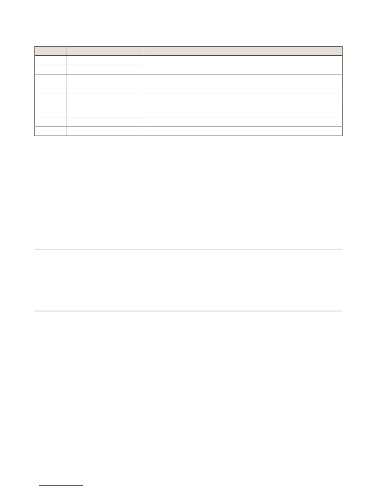
Pin Parameter Description
Pin 6 Primary RS-485 –
Running Modbus protocol at 19.2k baud, use this bus to connect to other Modbus
Slave devices. The
DXM100 Controller is a Modbus Master device on this RS-485 port.
Pin 7 Primary RS-485 +
Pin 9 RS-232 Tx
Serial RS-232 connection. This bus must use a ground connection between devices to
operate correctly.
Pin 10 RS-232 Rx
Pin 13 Secondary RS-485 –
The DXM100 Controller is a Modbus slave on this bus (see I/O Base Board Connections
on page 13).
Pin 14 Secondary RS-485 +
Pin 15 CANL –
Pin 16 CANH +
3.3 Modbus RTU Master/Modbus RTU Slave
The
DXM100 Controller can be a Modbus RTU master device to other slave devices and can be a Modbus slave device to
another Modbus RTU master. The DXM100 Controller uses the primary RS-485 port (pins 6 and 7) as a Modbus RTU
master to control external slave devices. The secondary port (pins 11 and 12) is the Modbus RTU slave connection.
• As a Modbus RTU master device, the DXM100 Controller controls external slaves connected to the primary RS-485
port, the local ISM radio, local I/O base board, and the local display board.
• As a Modbus RTU slave device, the DXM100 Controller local registers can be read from or written to by another
Modbus RTU master device.
Use the DXM Configuration Tool to define operational settings for both the Modbus RTU master port and the Modbus RTU
slave port.
3.4 Ethernet
Before applying power to the DXM100 Controller, verify the Ethernet cable is connected. If the Ethernet cable is not
connected when the device powers up, the DXM100 Controller will not recognize the connection.
The Ethernet connection supports the DXM Configuration Tool, Modbus/TCP, and EtherNet/IP. ScriptBasic also has access
to Ethernet for custom programming. Use the DXM Configuration Tool to configure the characteristics of the Ethernet
connection, fixed IP addresses, DHCP, etc. The LCD menu allows the user to change the IP Address.
3.5 Modbus Master Port and Slave Port
There are two RS-485 ports on the DXM Controller, a Modbus master RS-485 port and a Modbus slave RS-485 port.
The Modbus master RS-485 is controlled by the
DXM Controller, which acts as the Modbus master. All wired devices
connected to the master RS-485 port must be slave devices.
The Modbus slave RS-485 port is controlled by another Modbus master device, not the DXM Controller. The slave port is
used by other devices that want to access the DXM Controller as a Modbus slave device. All local registers are available to
be read or written from this slave port. Set the Modbus Slave ID for the secondary RS-485 port using the LCD display
menu: System > DXM Slave ID.
3.5.1 Modbus Master and Slave Port Settings
The basic communications parameters for the RS-485 ports are set in the DXM Configuration Tool and are saved in the
XML configuration file. All basic settings are available under Settings > General screen of the DXM Configuration Tool.
Master port parameters include:
• Baud rate and parity
• Set the Communications Timeout parameter to cover the expected time for messages to be sent throughout the
wireless network. For the DXM Controller, the Communications Timeout parameter is the maximum amount of
time the DXM Controller should wait after a request is sent until the response message is received from the Modbus
slave device.
• Maximum Polling Rate sets the minimum wait time from the end of a Modbus transaction to the beginning of the
next Modbus transaction.
DXM100 Controller Instruction Manual
16 www.bannerengineering.com - Tel: 763.544.3164

 Loading...


