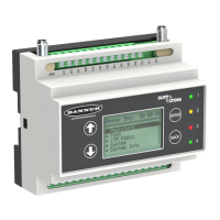
7.4 I/O Base Board (Modbus Slave 200)
Base Board Input Connection
Modbus Register Description
1 Universal input 1
2 Universal input 2
3 Universal input 3
4 Universal input 4
Base Board Output Connection
Modbus Register Description
501 NMOS Output 1
502 NMOS Output 2
503 NMOS Output 3
504 NMOS Output 4
505 Switched Power 1 (5 V or 16 V)
506 Switched Power 2 (5 V or 16 V)
507 DAC Output 1
508 DAC Output 2
7.4 Input/Output Parameter Modbus Registers
Universal Input Parameter Modbus Registers
Universal Inputs 1 2 3 4
Enable Full Scale 3303 3323 3343 3363
Temperature °C/°F 3304 3324 3344 3364
Input Type 3306 3326 3346 3366
Threshold 3308 3328 3348 3368
Hysteresis 3309 3329 3349 3369
Enable Rising 4908 4928 4948 4968
Enable Falling 4909 4929 4949 4969
High Register for Counter 4910 4930 4950 4970
Low Register for Counter 4911 4931 4951 4971
Enable Full Scale.
Set to 1 to enable a linear range from 0 to 65535 for specified input range. For a 4 to 20 mA input, a
value of 0 represents 4 mA and 65535 represents 20 mA. Set this parameter to 0 to store input readings in unit-specific
data. For example, the register data representing a 15.53 mA reading is 15530. For units of current (0 to 20 mA inputs),
values are stored as µA (micro Amps) and voltage values are stored as mV (millivolts).
Enable Rising/Falling. Use these registers to enable the universal input logic to count on a rising transition or a falling
transition. Write a one (1) to enable; write a zero (0) to disable.
High/Low Register for Counter. The low and high registers for the counter hold the 32-bit counter value. To erase the
counter, write zeroes to both registers. To preset a counter value, write that value to the appropriate register.
Hysteresis and Threshold. Threshold and hysteresis work together to establish the ON and OFF points of an analog
input. The threshold defines a trigger point or reporting threshold (ON point) for a sensor input. Setting a threshold
establishes an ON point. Hysteresis defines how far below the threshold the analog input is required to be before the input
is considered OFF. A typical hysteresis value is 10% to 20% of the unit’s range.
DXM100 Controller Instruction Manual
www.bannerengineering.com - Tel: 763.544.3164 47

 Loading...