4 Working with Modbus Devices
4.1 Overview
The DXM Controller has two physical RS-485 connections using Modbus RTU protocol.
The master Modbus RS-485 port is for the
DXM Controller to act as a Modbus master device to control internal and
external Modbus slave devices.
The Modbus master RS-485 port is labeled M+, M- on the DXM Controller. The Modbus slave port is used when another
Modbus master device wants to communicate with the DXM Controller when the DXM Controller is a Modbus slave device.
The Modbus slave RS-485 port is labeled S=, S1 on the DXM Controller.
Ethernet
Modbus RS-485
(slave
port)
Processor Modbus
Control/Data
External
Modbus
Slaves (2-10)
Modbus RS-485
(master port)
Modbus
SID
199
Modbus
SID
1
Modbus
SID
201
Modbus
SID
200
Local
Registers
GW/MH
Radio
Display I/O Base
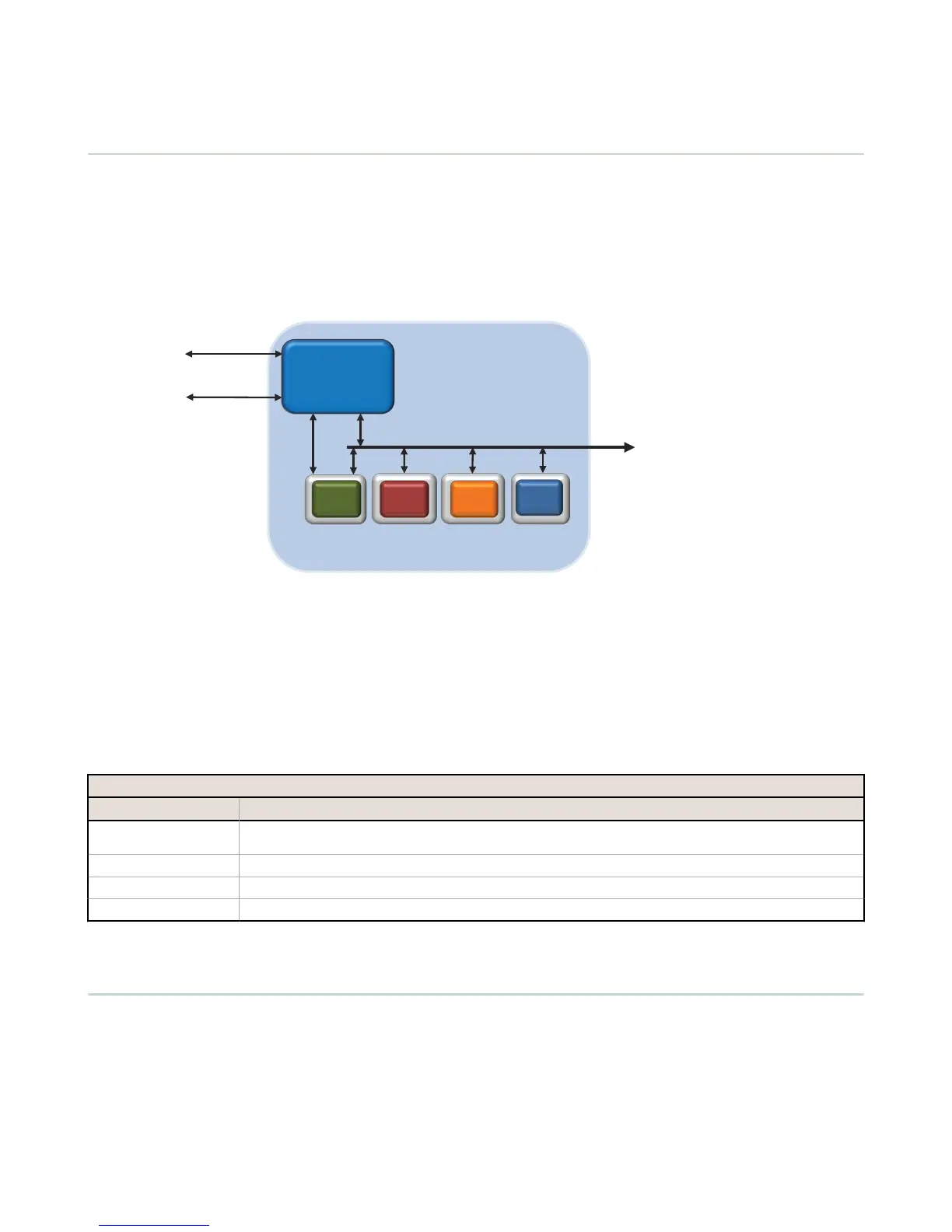
The DXM Controller has dual Modbus roles: a Modbus slave device and a Modbus master device. These run as separate
processes.
The Modbus slave port allows access into the
DXM Controller local registers. To operate as a Modbus slave device, the DXM
Controller needs to be assigned a unique Modbus slave ID as it pertains to the host Modbus network. This slave ID is
separate from the internal Modbus slave IDs the DXM Controller uses for its own Modbus network. The DXM Modbus slave
ID is defined through the LCD menu. Other Modbus slave port parameters are defined by using the DXM Configuration
Tool.
The DXM Controller operates the Modbus master port. Each device on the master port must be assigned a unique slave ID.
There are slave IDs that are reserved for internal devices in the DXM Controller.
DXM Internal Modbus Slave IDs (factory default)
Modbus Slave ID Device
1 Gateway (PE5) or MultiHop (HE5) ISM Radio—MultiHop wireless devices connected to the internal MultiHop radio should
be assigned Modbus Slave addresses starting at 11.
199 Local Registers—Internal storage registers of the DXM Controller
200 I/O Base Board—All data and parameters for each input or output of the DXM Controller.
201 LCD Display—The user has access to the LED indicators on the DXM Controller.
4.2 Assigning Modbus Slave IDs
4.2 DXM Modbus Slave ID
Assign the DXM Modbus Slave ID only if a Modbus master device is reading or writing the
DXM Controller Local Register
data through the Modbus RS-485 slave port (S+, S-).
Set the DXM Slave ID from the LCD menu under System > DXM Slave ID. The DXM Controller can have any unique slave
ID between 1 and 246, depending upon the host Modbus network. Other RS-485 slave port parameters are set in the DXM
Configuration Tool under the Settings > General tab.
DXM100 Controller Instruction Manual
18 www.bannerengineering.com - Tel: 763.544.3164

 Loading...


