3.2 Applying Power to the DXM100 Controller
Apply power to the DXM100 Controller using either 12 to 30 V dc or a 12 V dc solar panel and 12 V sealed lead acid
battery
operating together.
The DXM100 has three power input and three power output options:
• For inputs
◦ 12 to 30 V dc
◦ 12 to 30 V dc solar panel
◦ 12 V dc sealed lead acid battery with automatic charging
• For outputs
◦ One 5 V dc fixed
◦ Two 5 V dc or 16 V dc switched
The DXM Controller continuously monitors the health of the power inputs. If a power input fault is detected, the DXM
Controller automatically switches over to battery with continuous uninterrupted operation.
If the incoming voltage drops below 11.2 V, the cellular modem does not turn on and will not turn on until the voltage is
above 11.8 V. A text file (CmVMon.txt) on the internal micro SD card saves the periodic sampling of the incoming voltage.
If cellular operation stops because of voltage, it is logged in this file.
The DXM Controller automatically charges the sealed acid battery. The charging algorithm is designed to work with a
sealed lead acid (SLA) battery only.
• When using 12 to 30 V dc , connect the 12 to 30 V dc + to pin 2 and connect the ground to pin 3.
• When using main dc power with a back up battery (default configuration), connect the incoming main power pin 2
(+) and to pin 3 (-). Connect the 12 V sealed lead acid battery to pin 4 (+) and pin 5 (-). The incoming main power
must be 15 to 30 V dc to charge the battery.
• When using a solar panel, connect the solar panel output to pin 2 and connect the ground to pin 3. Connect the 12
V dc SLA battery to pin 4 (+) and pin 5 (-). To change the charging algorithm, refer to Supplying Power from Solar
(B1 and S1).
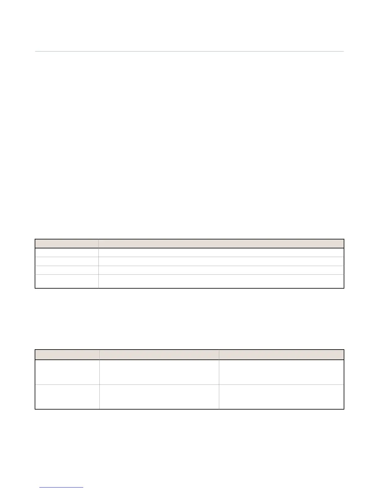
Pin Description
Pin 1 No connection
Pin 2 12 to 30 V dc input (+) or solar panel connection (+)
Pins 3, 5, 8, 17, 26, 29 Main logic ground for the DXM100 Controller
Pin 4 Solar or backup battery positive input. Battery voltage must be less than 15 V dc. Use only a sealed lead acid (SLA)
battery.
3.2 Using Courtesy Power or Switch Power
Pin 18 of the
DXM100 Controller is a constant power source that supplies 5 volts up to 500 mA.
Pins 21 (switch power 2) and 30 (switch power 1) are switched power outputs. Configure the switched power outputs using
Modbus registers. The output voltage can be either 5 volts or 16 volts and is controlled using a Modbus register on the I/O
board (Modbus slave ID 200).
Switch Power Enable Register Voltage Register
1 (pin 30)
2201
Write a 0 to turn OFF
Write a 1 to turn ON (default)
3601
Write a 0 to select 5 V (default)
Write a 1 to select 16 V
2 (pin 21)
2251
Write a 0 to turn OFF
Write a 1 to turn ON (default)
3621
Write a 0 to select 5 V (default)
Write a 1 to select 16 V
3.2.1 Supplying Power from 12 to 30 V dc and a Battery Backup
The factory default setting for the battery charging algorithm assumes you are using
12 to 30 V dc to recharge the battery.
DXM100 Controller Instruction Manual
14 www.bannerengineering.com - Tel: 763.544.3164

 Loading...


