1 DXM Overview
1.1 DXM System Overview
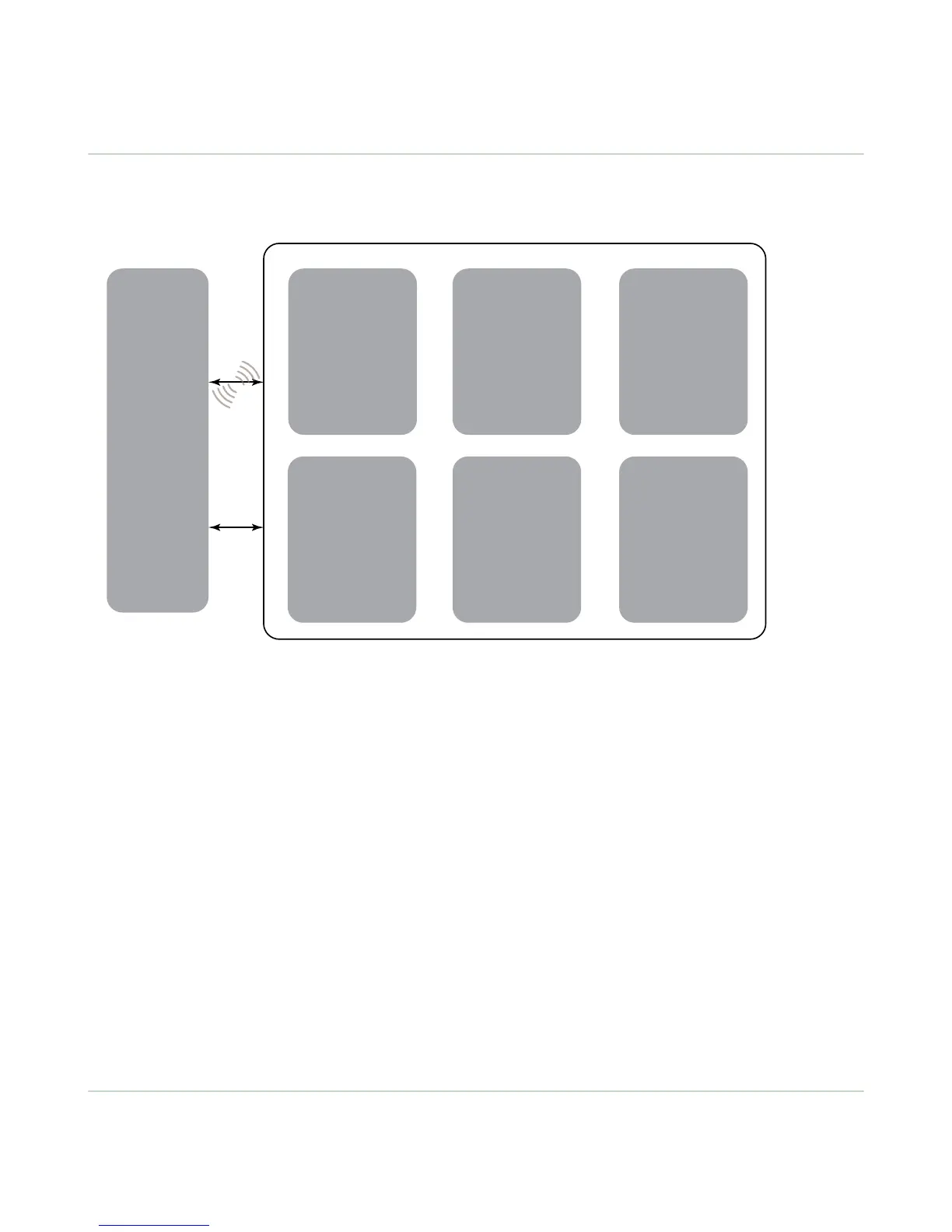
Banner's DXM Logic Controller integrates Banner's wireless radio, cellular connectivity, and local I/O to provide a platform
for the Industrial Internet of Things (IIoT).
Automation
Systems
HMI
PLC
Historian
Cloud
Sensor
Indicator
Machine
Control
Connectivity
Banner Wireless
USB
Ethernet
Cellular
RS-485 Master
RS-485 Slave
User Interface
LCD Screen
LED Indicators
I/O
4 to 20 mA
0 to 10
V
PNP/NPN Discrete
Counter
Temp
Potentiometer
Logic Controller
Action Rules
T
ext Prog. Language
Scheduler
Automation
Protocols
Modbus RTU
Modbus TCP
EtherNet/IP
Internet
Messaging
Push data to the cloud
Data Logging
SMS T
ext and EMail
HTTP API
The DXM Controller's wired and wireless connectivity
options make it easy to share data between local and remote
equipment. The cellular modem option eliminates the need for IT infrastructures to connect remote equipment for sensing
and control. The integrated Sure Cross
®
wireless radio enables Modbus connectivity to remote sensors, indicators, and
control equipment.
The DXM Controller incorporates several automation protocols into its system, including:
• Modbus RTU—Integrates into existing RS-485 serial-based Modbus-enabled automation systems.
• Modbus TCP—Uses Ethernet to attach to existing Modbus-enabled automation systems.
• EtherNet/IP—Automation systems that use the EtherNet/IP protocol can directly attach to the DXM Controller using
Ethernet.
Internet messaging tools share information generated by sensors, indicators, and control equipment with automation
systems and personnel. When Internet messaging is used in combination with the logic controller, the DXM Controller can
generate and send historical data logs, alerts, and alarms using Ethernet or cellular connectivity options. Banner's API
interface allows the user to create connections with web-based automation or business systems.
Program the DXM Controller's logic controller using action rules and text language, which can execute concurrently. The
control functions allow freedom when creating custom sensing and control sequences. The logic controller supports the
Modbus protocol standards for data management, ensuring seamless integration with existing automation systems.
On-board universal and programmable I/O ports connect to local sensors, indicators, and control equipment.
A simple user interface consists of an LCD screen and four LED indicators. Use the LCD to access system status and
setup, view user selectable events or data, and to bind and perform site surveys for Sure Cross radios. Configure the user
programmable LEDs to indicate the status of the DXM Controller, processes, or equipment.
1.2 DXM Automation Protocols
The DXM Controller supports the following automation protocols.
DXM100 Controller Instruction Manual
www.bannerengineering.com - Tel: 763.544.3164 3

 Loading...


