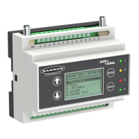
Solar panel and battery combinations for a DXM Controller system
Solar Panel Battery Capacity
3
Days of Autonomy DXM mA DXM Controller
20 watt 20 Ahr 10 days 35 mA DXM Controller with ISM radio and Cellular Modem
5.1 Monitoring Solar Operation
The DXM solar controller provides Modbus registers that allow the user to monitor the state of the solar panel input
voltage, the battery voltage, the charging current, and the temperature in °C. The
DXM Controller can be configured to
monitor the health of the charging system as well as send an alert message when the battery is too low.
The charts show a typical charging cycle, with each vertical grid representing about eight hours. The chart shows three
days of charging.
Figure 1. Solar Panel Voltage (mV) -- Cloudy First Day
Figure 2. Battery Voltage (mV) - Cloudy First Day
5.2 Inputs and Outputs
The I/O base board is a Modbus slave device (Slave ID 200) that communicates to the processor board using Modbus
commands. Use the
DXM Configuration Tool to create a configuration using read/write maps that will access inputs or
outputs on the I/O board.
Communication with the I/O board runs at a maximum rate of 10 ms per transaction. The parameter setting for the bus
with the I/O board and the processor board are fixed. External Modbus communication runs at a maximum rate of 50 ms
per transaction. The parameter settings for the external RS-485 buses are controlled by the DXM Configuration Tool.
Refer to the Modbus Registers section for more descriptions of each Modbus register on the DXM100 Controller.
5.2.1 Universal Inputs
The universal inputs on the DXM100 Controller can be programmed to accept several different types of inputs:
• Discrete NPN/PNP
• 0 to 20 mA analog
3
Battery capacity (amp hour) is standard amp rating taken for 20 hours. Battery capacity should be monitored for reliable system power and may
need to be increased for cold weather locations.
DXM100 Controller Instruction Manual
24 www.bannerengineering.com - Tel: 763.544.3164

 Loading...