2.2 ISM Radio Board (Modbus Slave ID 1)
The ISM radio board may be a MultiHop radio (DX80DR*M-HE5) or a Performance Gateway radio (DX80G*M2S-PE5). Refer
to the model number label on the
DXM100 Controller and the model number table to identify the ISM radio type.
The ISM radio should be plugged into the I/O base board
with the U.FL antenna connector closest to the SMA
connectors.
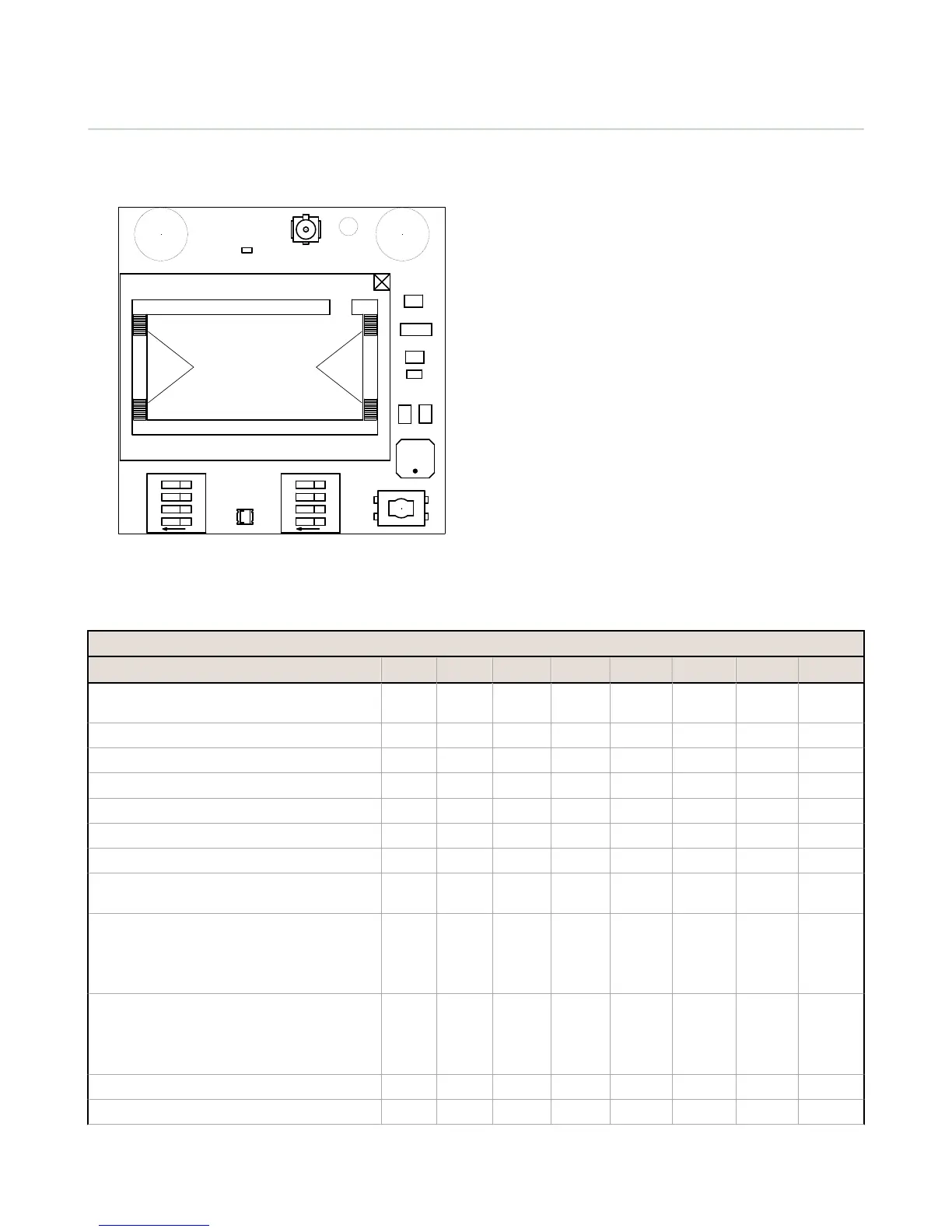
A - Antenna connector
B - Button
C - LED
D1 and D2 - DIP switches
2.2 MultiHop (HE5) DIP Switch Settings
Switches
Device Settings 1 2 3 4 5 6 7 8
Serial line baud rate 19200 OR User defined receiver
slots
OFF* OFF*
Serial line baud rate 38400 OR 32 receiver slots OFF ON
Serial line baud rate 9600 OR 128 receiver slots ON OFF
Serial line baud rate Custom OR 4 receiver slots ON ON
Parity: None OFF* OFF*
Parity: Even OFF ON
Parity: Odd ON OFF
Disable serial (low power mode) and enable the
receiver slots select for switches 1-2
ON ON
Transmit power
900 MHz radios: 1.00 Watt (30 dBm)
2.4 GHz radios: 0.065 Watts (18 dBm) and 60 ms
frame
OFF*
Transmit power
900 MHz radios: 0.25 Watts (24 dBm)
2.4 GHz radios: 0.065 Watts (18 dBm) and 40 ms
frame
ON
Application mode: Modbus OFF*
Application mode: Transparent ON
DXM100 Controller Instruction Manual
www.bannerengineering.com - Tel: 763.544.3164 7

 Loading...


