July 25, 2023page4
(1)
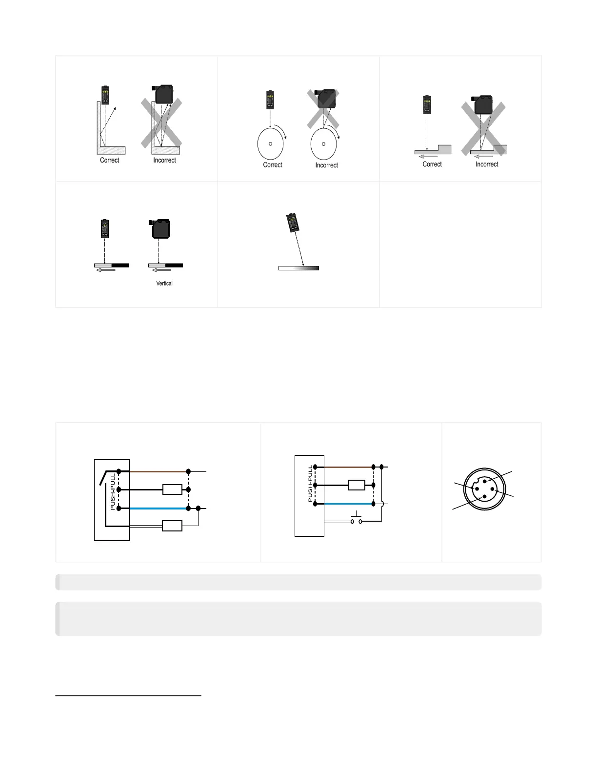
Applying tilt to sensor may improve performance on reflective targets. The direction and magnitude of the tilt depends on the application, but a 15° tilt is often
sufficient.
Q5X with Dual Discrete Outputs and IO-Link Quick Start Guide
Orientationbyawall
Orientationforamovingob
ject
Orientationforaheightdif
ference
Orientation for a color or
luster difference
Horizontal
Orientation
Orientation
(Optimal)
CC
Orientationforhighlyreflec
tive target
(1)
Reflective
Surface
(optional)
Mount the Device
Wiring Diagram
Channel 2 as PNP Discrete or PFM
Output
bk (4)
bn (1)
bu (3)
wh (2)
10-30 V DC
CH1
CH2
+
–
Load
Load
Channel2asRemoteInput
bk (4)
bn (1)
bu (3)
wh (2)
10-30 V DC
CH1
CH2
+
–
Load
Remote Input
NOTE: Openleadwiresmustbeconnectedtoaterminalblock.
NOTE: TheChannel2wirefunctionandpolarityisuserselectable.ThedefaultforthewireisPNPoutput.Refer to the
InstructionManual(p/n208794)fordetailsregardinguseasaremoteinputorpulsefrequencymodulation(PFM)out
put.
Ifabracketisneeded,mountthedeviceontothebracket.
Mount the device (or the device and the bracket) to the machine or equipment at the desired location. Do not tighten the mounting
screwsatthistime.
Checkthedevicealignment.
Tightenthemountingscrewstosecurethedevice(orthedeviceandthebracket)inthealignedposition.
© Banner Engineering Corp.

 Loading...