3. Check the device alignment.
4. Tighten the mounting screws to secure the device (or the device and the bracket) in the aligned position.
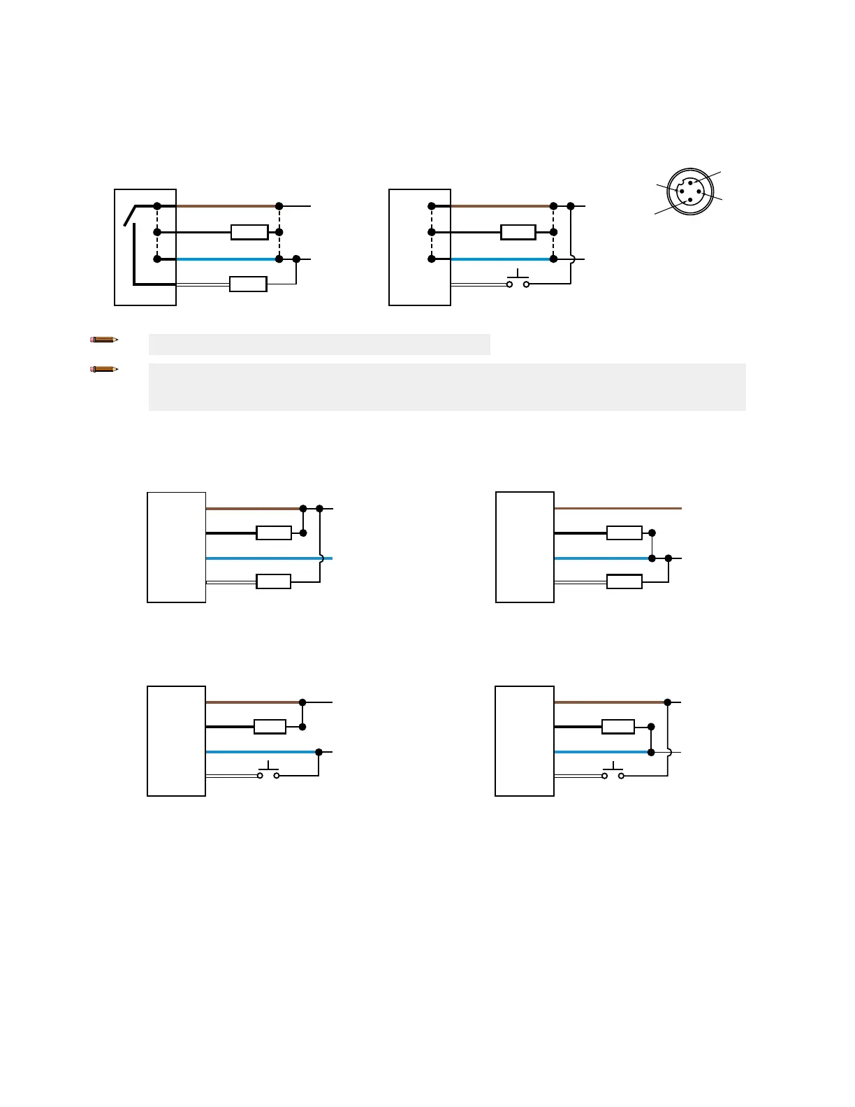
Wiring Diagram
Figure 12. Channel 2 as PNP Discrete or PFM Output
bk (4)
bn (1)
bu (3)
wh (2)
10-30 V DC
CH1
CH2
+
–
PUSH-PULL
Load
Load
Figure 13. Channel 2 as Remote Input
bk (4)
bn (1)
bu (3)
wh (2)
10–30 V DC
CH1
CH2
+
–
PUSH-PULL
Load
Remote
Input
Note: Open lead wires must be connected to a terminal block.
Note: The Channel 2 wire function and polarity is user-selectable. The default for the wire is PNP output. Refer
to the Instruction Manual (p/n 208794) for details regarding use as a remote input or pulse frequency
modulation (PFM) output.
NPN Discrete Outputs
Figure 14. Channel 1 = NPN Output, Channel 2 = NPN Output
bk (4)
bn (1)
bu (3)
wh (2)
10–30 V DC
CH1
CH2
+
–
Load
Load
PNP Discrete Outputs
Figure 15. Channel 1 = PNP Output, Channel 2 = PNP Output
bk (4)
bn (1)
bu (3)
wh (2)
10–30 V DC
CH1
CH2
+
–
Load
Load
NPN Output and Remote Input
Figure 16. Channel 1 = NPN Output, Channel 2 = NPN Remote Input
bk (4)
bn (1)
bu (3)
wh (2)
10–30 V DC
CH1
CH2
+
–
Load
Remote
Input
PNP Output and Remote Input
Figure 17. Channel 1 = PNP Output, Channel 2 = PNP Remote Input
bk (4)
bn (1)
bu (3)
wh (2)
10–30 V DC
CH1
CH2
+
–
Load
Remote
Input
Cleaning and Maintenance
Clean the sensor when soiled and use with care.
Handle the sensor with care during installation and operation. Sensor windows soiled by fingerprints, dust, water, oil, etc. may create
stray light that may degrade the peak performance of the sensor. Blow the window clear using filtered, compressed air, then clean
as necessary using only water and a lint-free cloth.
Q5X Laser Measurement Sensor with Dual Discrete Outputs and IO-Link
4 www.bannerengineering.com - Tel: + 1 888 373 6767 P/N 208795 Rev. G

 Loading...