R5900103 /02 C-10, C-534
Dimensions (HxWxD) 14.6 mm x 59.3 mm x 161.39 mm / 0.57” x 2.354” x 6.354”
Power consumption Powered over USB
5V DC
350mA Typical
500mA Maximum
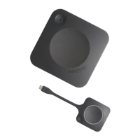
2.3 About the Base Unit
Base Unit functionality
The Base Unit receives the wireless input and controls the content of the meeting room display.
The Base Unit can be put on the meeting room table or mounted on a wall or ceiling. Check the installation
guide for instructions on how to install the Base Unit.
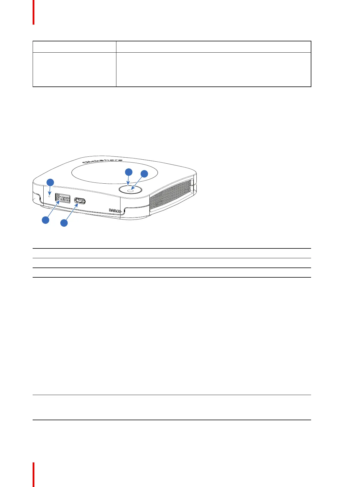
Image 2–3
1 USB Type-A port (USB 2.0)
2 USB Type-C port (USB 2.0)
3 Status LED ring
4 Standby button
5 Hardware reset button
USB ports
The USB Type-C
TM
is used to pair the (optional) available Buttons. The USB Type-C
TM
and USB Type-A can
be used to update the Base Unit firmware when not done via XMS.
When plugging in the (optional) Button into the Base Unit, the Button is paired to the Base Unit. The Base Unit
checks whether the software and firmware of the Button is up to date. If not, the Base Unit updates the
software and/or firmware.
The use of a convertor is sometimes necessary to connect to one of these ports.
Status LED ring
The color of the LED ring around the power button of the Base Unit give information on the status of the
system.
LEDs behavior Explanation
static red
• receiving content from the Button and streaming towards the
display.
• during the first phase of the Base Unit boot process.
blinking white
• system is starting up (during the second phase)
• Button pairing is in progress
• software update of the Base Unit
C-10, C-5 Specifications
 Loading...