Manual 2100-769A
Page 24 of 50
Wiring – Main Power
All models are suitable only for connection with copper
wire. Each unit and/or wiring diagram will be marked
“Use Copper Conductors Only”. These instructions
must be adhered to. Refer to the National Electrical
Code (NEC) for complete current carrying capacity data
on the various insulation grades of wiring material. All
wiring must conform to NEC and all local codes.
The electrical data on the serial plate, in the unit
specications and also in Table 13 on page 43 list fuse
and wire sizes (75°C copper) for all models including
the most commonly used heater sizes. Also shown are
the number of eld power circuits required for the
various models with heaters. The unit rating plate lists
a “Maximum Time Delay Relay Fuse” or circuit breaker
that is to be used with the equipment. The correct type
and size must be used for proper circuit protection and
also to ensure that there will be no nuisance tripping
due to the momentary high starting current of the
compressor motor.
Three phase models must have proper phasing. A phase
monitor is included in all three phase models, and will
indicate improper phasing during a call for heating
or cooling (24VAC at Y1 terminals). See provided
information included in this document regarding the
phase monitor.
High Voltage Connections
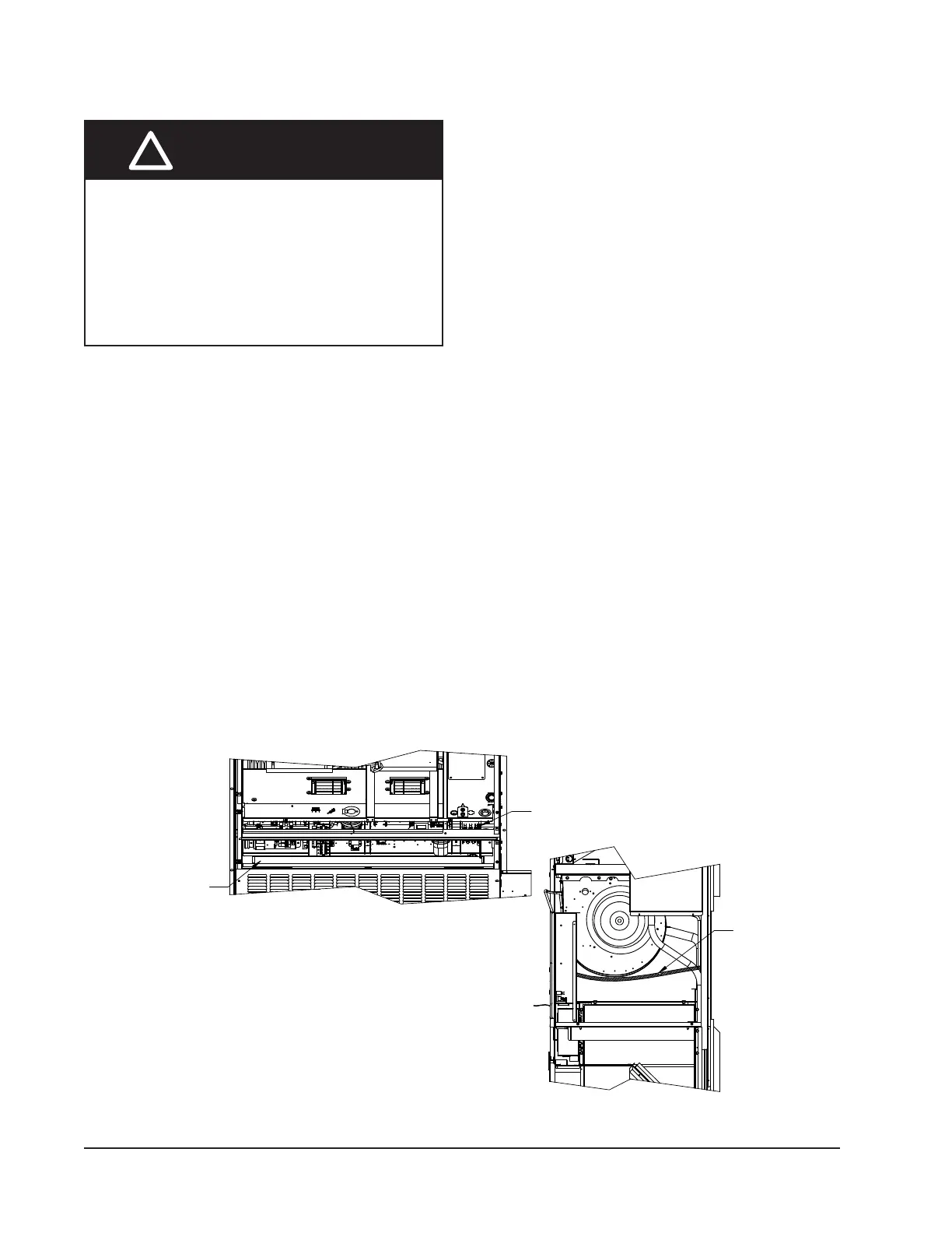
Route eld wires under the eld wire shield shown in
Figure 19. (The eld wire shield can be removed for wire
installation.) If eld power is supplied to the left side
of the unit, run the high voltage wires under the shield
shown in Figure 19 and to the right of the wire shield
next to the compressor contactor and up into the upper
Main electrical power must be supplied to the unit
from a clean, reliable power source. Verify voltage being
supplied to the unit is consistent during all times of the
day and within the range specied for the unit in the
unit specications and on the unit serial plate. Voltage
must be measured at the eld power connection point
in the unit and while the unit is operating at full load
(maximum amperage operating condition).
Refer to the unit serial plate for maximum fuse or circuit
breaker size. Reference the unit specication sheet for
wire sizing information. Each outdoor unit is marked
with a “Minimum Circuit Ampacity”. This means that
the eld wiring used must be sized to carry that amount
of current. Depending on the installed KW of electric
heat, there may be two eld power circuits required. If
this is the case, the unit serial plate will so indicate.
MIS-4044 A
USE CONDUIT
WHEN FIELD WIRES
COME IN THROUGH
THE BACK
RIGHT SIDE VIEW
WIRE SHIELD
FIELD HIGH OR LOW
VOLTAGE WIRE SHIELD
FRONT VIEW
FIGURE 19
High Voltage Connections
USE CONDUIT
WHEN FIELD WIRES
COME IN THROUGH
THE BACK
RIGHT SIDE VIEW
WIRE SHIELD
FIELD HIGH OR LOW
VOLTAGE WIRE SHIELD
FRONT VIEW
MIS-4044A
Electrical shock hazard.
Do not operate this equipment without an
earth ground attached and always disconnect
the remote electric power supplies before
servicing.
Electrical shock can result in serious injury or
death.
!
WARNING


 To Next Page