Manual 2100-769A
Page 44 of 50
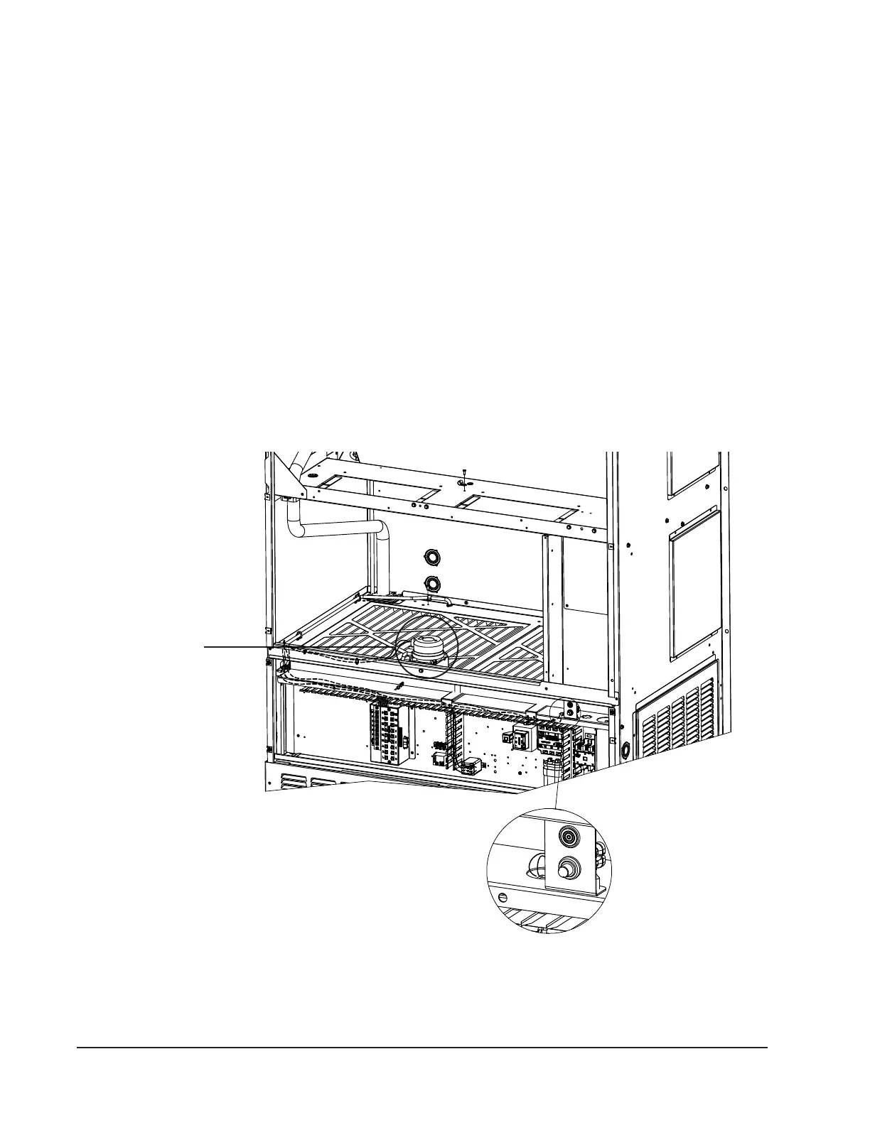
FIGURE 29
Dirty Filter Switch and Dirty Filter Indicator Light/Reset Switch
Dirty Filter Switch
Dirty Filter Indicator Light
and Reset Swtitch
Unit Airflow
These units are equipped with a variable speed (ECM)
indoor motor that automatically adjusts itself to
maintain approximately the same rate of indoor airow
in both heating and cooling, dry and wet coil conditions
and at both 230/208 or 460 volts.
An additional feature of the system is the possibility to
reduce the airow by 10%. This can be accomplished
by disconnection of blower motor low voltage wire
coming from PIN 10 and connected to the "R" terminal
of the defrost board. If this wire is disconnected, use
electrical tape to cover end of connector to prevent
short-circuiting. The 10% reduction will only be
adjusted when unit is running in cooling mode. In
heating mode the blower will remain at rated airow.
Dirty Filter Switch
1. Disconnect all power to the unit. Remove control
panel outer cover and upper front panel.
2. The dirty lter switch is located on top of the lter
partition between the blower wheels (see Figure
29). The dirty lter indicator light and reset switch
is located on the right side of the lter access
opening above the control panel. Remove the cover
on the dirty lter switch and ensure the knob is
set at 0.4" W.C. (see Figure 30). This is only a
recommended starting point prior to making switch
adjustments. Switch setting is highly dependent
on lter type used, blower speed, unit ducting and
other unit installation characteristics. See Dirty
Filter Switch Adjustment for instructions on how to
make proper switch adjustments.
3. Re-install upper front panel.