Manual 2100-597G
Page 36 of 68
1.
Open front swinging doors of main unit (by popping
front door latches).
2. Throw main power disconnect to the
“
OFF
”
position to eliminate risk of injury or death due to
electrical shock.
3. Remove five (5) screws holding front CRV door in
place (see Figure 21).
4. Locate
“
Brown Wire with White Trace
”
that has
a black terminal on the end where it connects to
the terminal strip (see Figure 20).
5. Move
“
Brown Wire with White Trace
”
to the
corresponding CFM level needed in accordance
with Figure 20.
WARNING
• Hazard of electrical shock.
• Electrical shock can result in serious
injury or death.
• Disconnect the remote electric power
supply or supplies before servicing.
corresponding CFM needed for the intake and exhaust
blowers to meet the design criteria and determine
which “speed/wire color” is needed. Then, perform the
following steps.
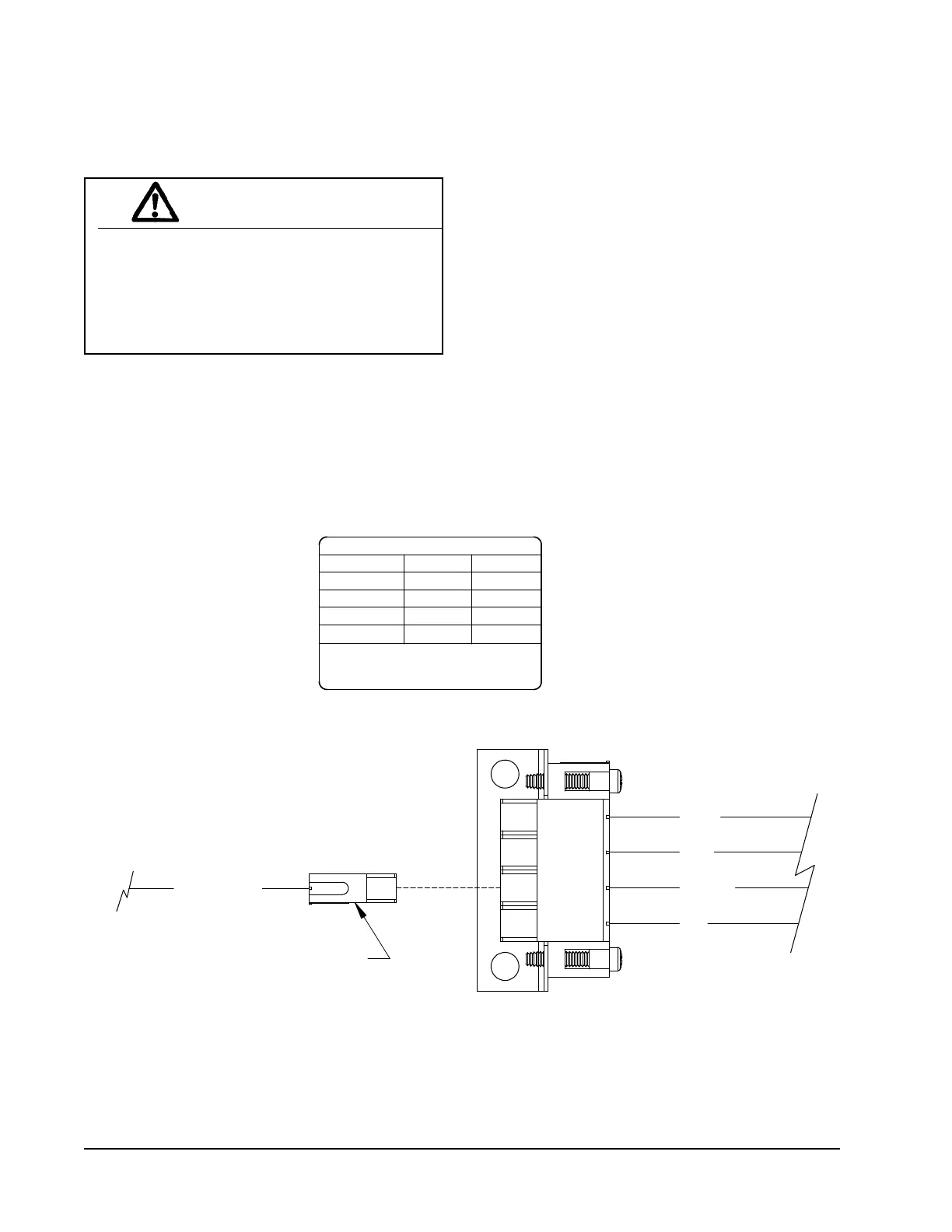
FIGURE 20
CRV Motor Speed/CFM Configuration
MED. HI
7961-7554
MOTOR SPEEDS
LO
MED. LO
HI
ORANGE
VENT OPTION INTAKE/EXHAUST SPEEDS
BROWN/WHITE
BLACK
BLUE
ORANGE
NOM. CFM
BLACK
BLUE
WIRE COLOR SPEED
RED
WIRE WITH WHITE TRACE.
300
375
450
525
LO
MED-LO
MED-HI
HI
RED
Move brown/white wire to corresponding motor
speed for required ventilation CFM. Factory
setting is Medium Lo (375 CFM).
TO CHANGE SPEEDS, MOVE BROWN
7961-755-2
MIS-3022 A