Manual 2100-597G
Page 66 of 68
FAN BLADE SETTING DIMENSIONS
The position of the fan blade should be flush with the
leaving face of the orifice plate. Check to make sure
the blades do not extend beyond the rear casing of the
unit. Spin the blade by hand to make sure it does not
hit the ring.
MODE of
OPERATION
OFF
Continuous
Blower
(Ventilation
Mode)
Part Load
Cooling
Full Load
Cooling
Dehum.
Mode
(when
equipped)
Part
Load
Heat
Pump
Full
Load Heat
Pump
Heat Pump
Full Load w/
1st Bank of
Elec. Heat
Heat Pump Full
Load w/ 1st &
2nd Bank of
Elec. Heat
Emergency
Heat Mode
Thermostat
24 VAC
Inuput Signals
— "G"
"G",
"Y1","Y2"
"G",
"Y1","Y2"
"D"
"G", "B",
"Y1"
"G", "B",
"Y1", "Y2"
"G", "Y1",
"Y2", "B",
"W1"
"G", "Y1", "Y2",
"B", "W2",
"W3"
"G",
"W2", "W3"
Pin #1 24 VAC "C" (Common) Signal, Always Energized
Pin #2 X
Pin #3 24 VAC "C" (Common) Signal, Always Energized
Pin #4 Not Used
Pin #5 Not Used
Pin #6 X X X X X X X
Pin #7 Not Used
Pin #8 Not Used
Pin #9 X X X
Pin #10 Not Used
Pin #11 Not Used
Pin #12 24 VAC Hot "R" Signal, Always Energized
Pin #13 X X
Pin #14 X X X X X
Pin #15 X X X X X X X X X
Pin #16 Not Used
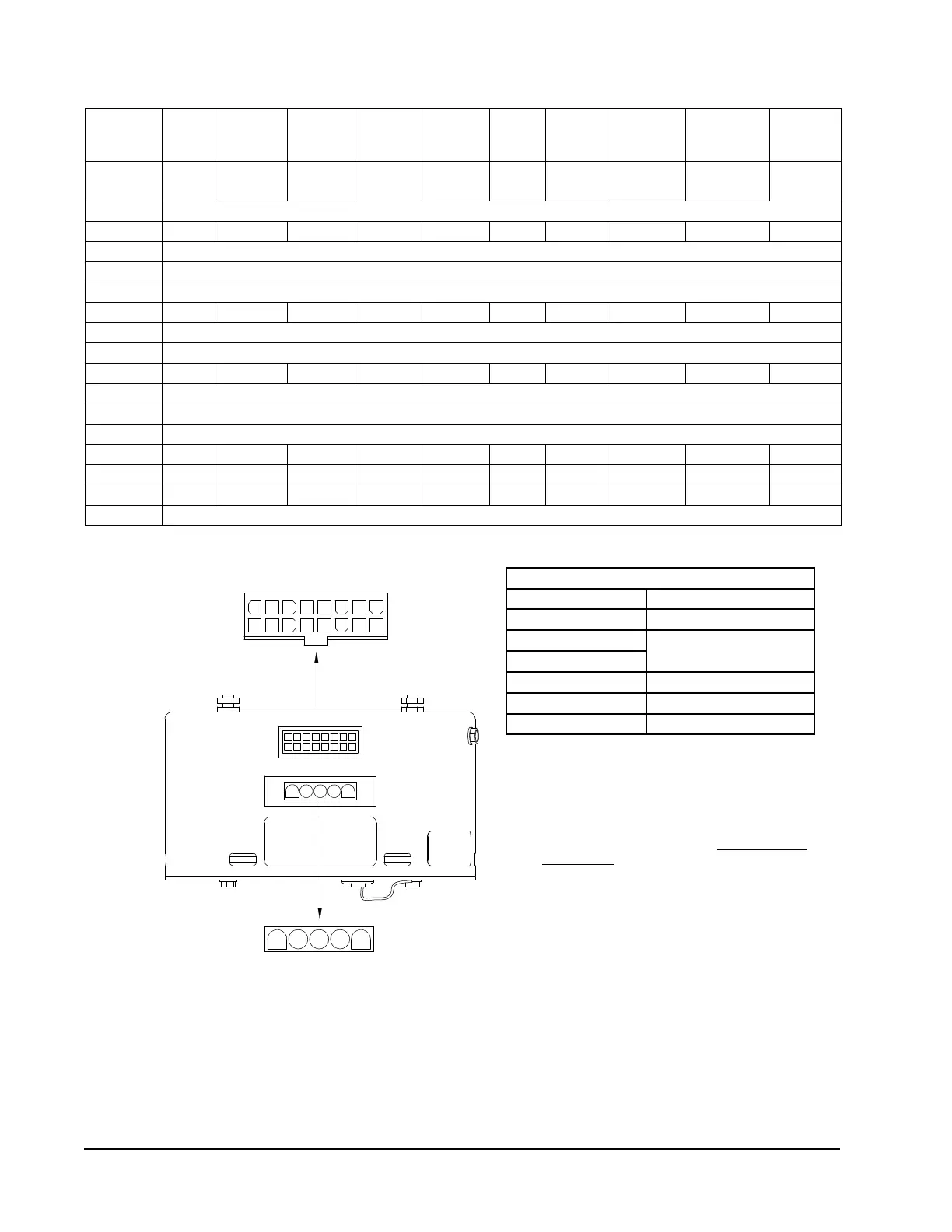
POWER CONNECTOR
PWB HEADER AMP 1-350945-0
PIN Description
1
Jumper Pin 1 to Pin 2 for
120VAC Line Input Only **
2
3 Chassis Ground
4 AC Line
5 AC Line
Troubleshooting ECM
™
Blower Motors
REFRIGERANT CHARGE
This unit was charged at the factory with the quantity
of refrigerant listed on the serial plate. AHRI capacity
and efficiency ratings were determined by testing with
this refrigerant charge quantity. The pressure tables
found on the following pages show nominal pressures
and temperatures for the units. Since many installa-
tion specific situations can affect the pressure read-
ings, this information should only be used by certified
technicians as a guide for evaluating proper system
performance. They shall not be used to adjust charge.
If charge is in doubt, reclaim, evacuate and recharge
the unit to the serial plate charge.
10
1 2 3 4 5 6 7 8
1615141312119
3 51 2 4
MIS-2839
FIGURE 39
Control Connector Motor Half
* Suggested mating connector
Housing — AMP 350809-1
Contact — AMP 350537-1
** WARNING — Applying 240VAC line input with
PIN 1 to PIN 2 jumper in place will permanently
damage unit!
Power Connector
Motor Half