Manual 2100-549G
Page 25 of 59
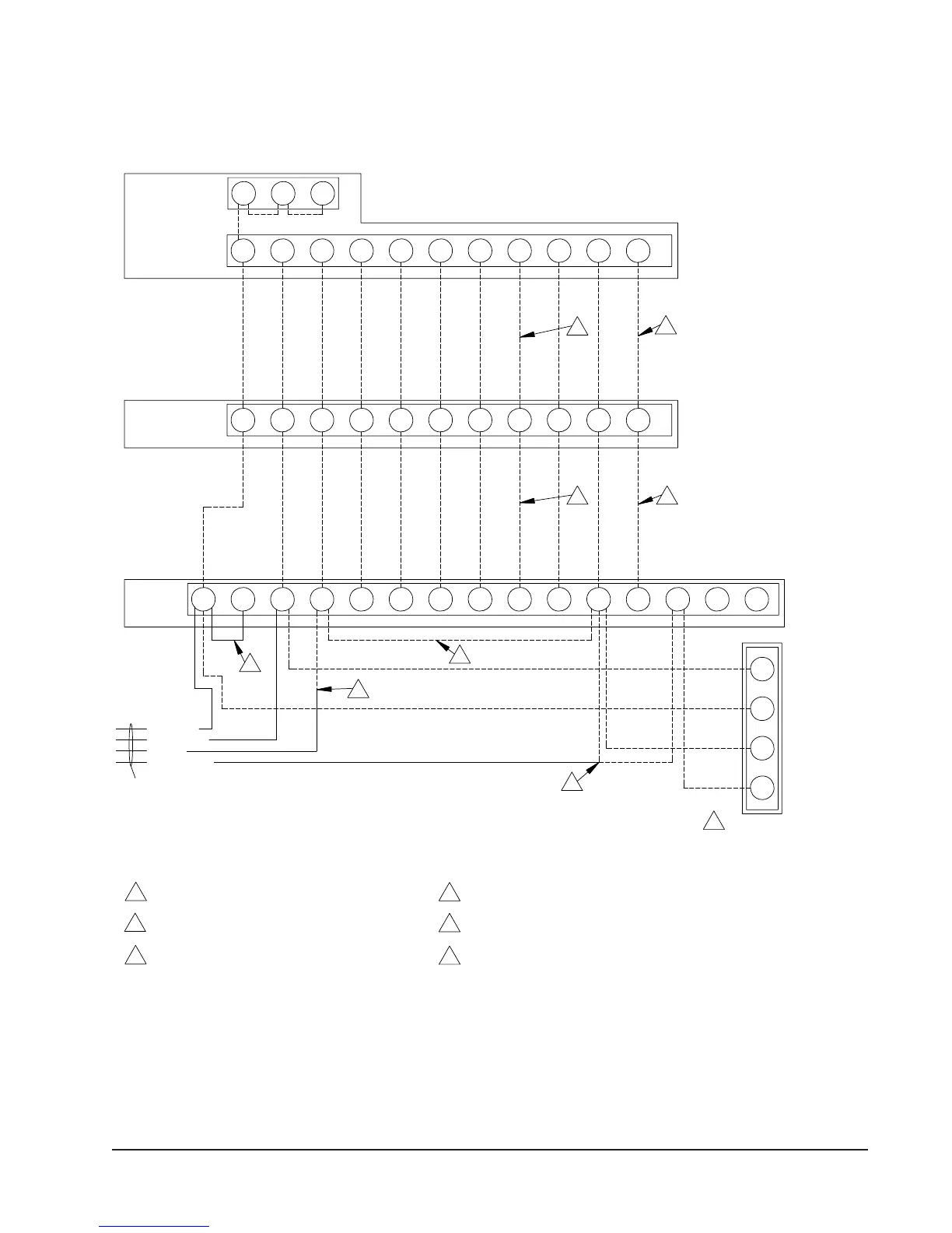
FIGURE 15
HEAT PUMP WITH CRV AND CO
2
CONTROL
SC
W1/E
ADLO/BY2Y1
24V
G
COM
W2
Completestat
Model #CS9B-THO or
Model #CS9BE-THO
SCSC
5
2
1
6
Thermostat
W1/E
A
YO/D
LO/BY2Y1RGCW2
Bard #8403-060
3
Low
MIS-3018
3
1
Additional wire required for dehumidification models.
2
Not needed below 15KW.
3
to N.C fire alarm circuit if emergency shutdown required.
Factory installed jumper. Remove jumper and connect
4 Connect to "G" terminal when thermostat has "Occupancy Signal".
Voltage
without "Occupance Signal" is used.
Install a jumper between "G" and "A" only when thermostat
5
4
5
CRV Wiring Harness
1
2
2 3
BROWN/WHITE
ORANGE
BLACK/WHITE
RED/WHITE
4W3 A DL
B/W1
Y2Y1RT GCW2
Term. Strip
R 6
directly to "A" and do not use seperate CO2 controller.
If CS9B-THOC or CS9BE-THOC is used, connect "Brown/White"
6
6
6
CO2 Control
Bard #8403-067
NOTE: Bard 8403-060
thermostat must be
in programmed
operation mode and
in programmed fan
mode for ventilation
to function.


 To Next Page