Manual 2100-549G
Page 5 of 59
TABLE 1
FACTORY BUILT-IN ELECTRIC HEAT TABLE
sledoM A-1H03I B-1H03I C-1H03I
A-1H63I
A-1H24I
B-1H63I
B-1H24I
C-1H63I
C-1H24I
A-1H84I
B-1H84I
B-1H06I
C-1H84I
C-1H06I
A-1H06I
WK
1-V042 1-V802 3-V042 3-V802 3-V064 1-V042 1-V802 3-V042 3-V802 3-V064 1-V042 1-V802 3-V042 3-V802 3-V064 1-V042 1-V802
HUTB HUTB HUTB HUTB HUTB HUTB HUTB HUTB HUTB HUTB HUTB HUTB HUTB HUTB HUTB HUTB HUTB
0.4 256,31932,01
0.5560,71997,21560,71997,21560,71997,21560,71997,21
0.6874,02953,51874,02874,02953,51874,02874,02953,51874,02
0.9717,03830,32717,03717,03830,32717,03717,03830,32717,03
0.01031,43895,52031,43895,52031,43895,52031,43895,52
0.51591,15693,83591,15693,83591,15591,15693,83591,15693,83591,15591,15693,83
0.81 434,16670,64434,16
0.02 062,86591,15062,86591,15
I-TEC Series General Information
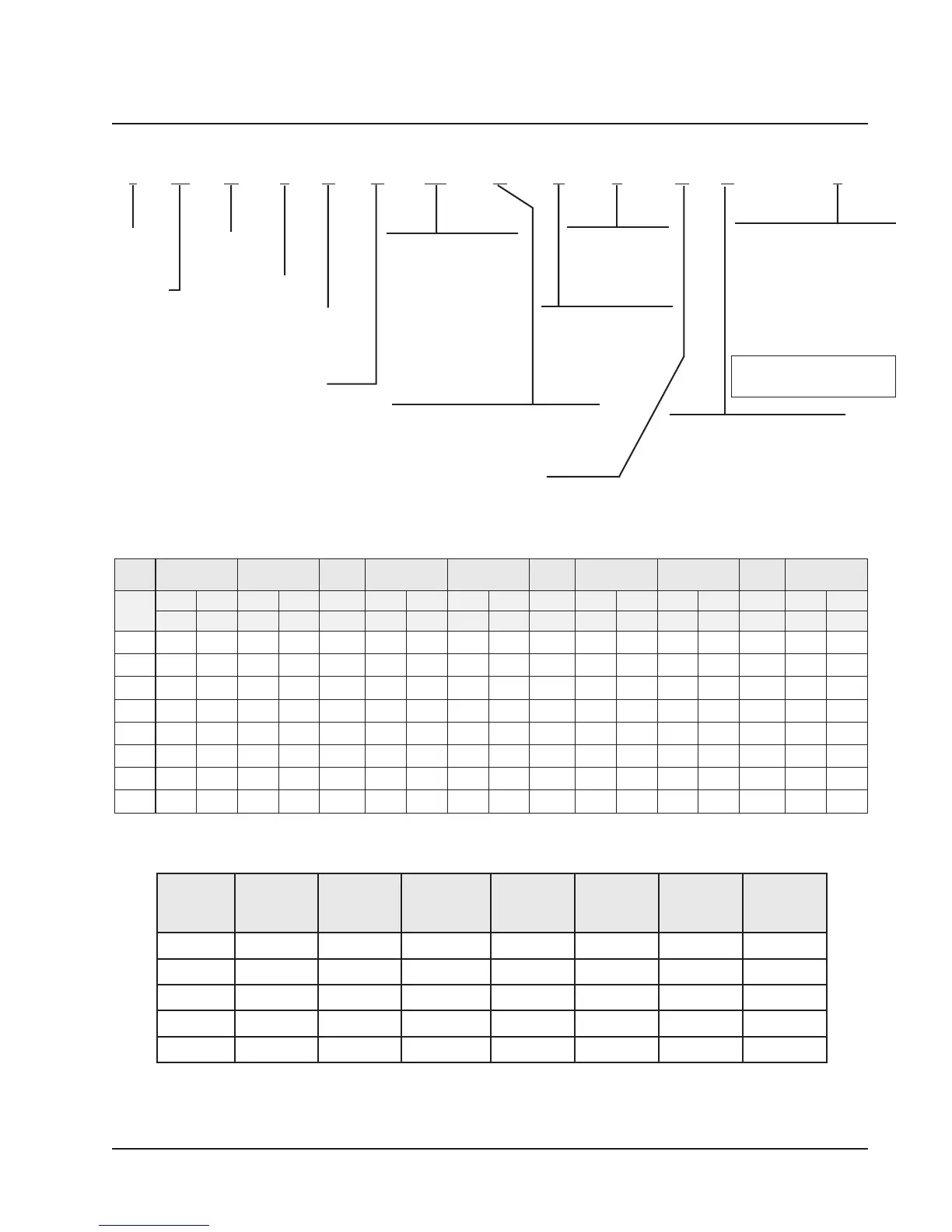
I-TEC MODEL NOMENCLATURE
I 36 H 1 D A 0Z R P 4 X X 2
SPECIAL UNITS
(–) = Standard
D = Dehum.
REVISION
VOLTS & PHASE |
A = 230/208, 60-1
B = 230/208, 60-3
C = 460-60-3
COIL TREATMENT
X - Std. Hydrophilic Fin Evap. &
Uncoated Alum. Cond. Coil
1 - Phenolic Coated ID Coil
2 - Phenolic Coated OD Coil
3 - Phenolic Coated ID & OD Coil
CONTROLS
X = 24V Terminal Block Only w/o
CompleteStat
1 = CompleteStat THO (Temp,
Humidity & Occupancy)
2 = CompleteStat THO w/CO2
3 = CompleteStat THO w/Ethernet
4 = CompleteStat THO w/CO2 &
Ethernet
MODEL
SERIES
NOMINAL
CAPACITY
30 = 30,000 BTUH
36 = 36,000
42 = 42,000
48 = 48,000
60 = 60,000
ELECTRIC HEAT
0Z = No heat w/breaker
04 = 4KW 1-Phase
05 = 5KW 1-Phase
06 = 6KW 3-Phase
09 = 9KW 3-Phase
10 = 10KW 1-Phase
15 = 15KW 1 & 3-Phase
18 = 18KW 3-Phase
20 = 20KW 1-Phase
VENTILATION OPTIONS
B = Blank-Off Plate
M = Multi-Speed CRV
N = Comb. CRV & DB Economizer
R=ERV
FILTER OPTIONS
P = 2" Pleated MERV 8
M = 2" Pleated MERV 11
N = 2" Pleated MERV 13
COLOR OPTIONS
X - Beige paint
1 - White paint
4 - Gray paint
SYSTEM TYPE:
HEAT PUMP
RESERVED
Note: CompleteStat must be field
installed & wired. All units have
24V terminal block.
1 Motor will deliver consistent CFM through voltage supply range with no deterioration.
2 Continuous fan CFM is the total air being circulated during continuous fan mode.
3 Will operate at rated Full Load Airflow when operating with Heat Pump.
4 Will occur automatically with a call for "W3" or "Emergency Heat" signal from the thermostat (Heat Pump Operation is
terminated at this condition).
TABLE 1A
INDOOR BLOWER PERFORMANCE
11
11
1
ledoM PSEdetaR PSE.xaM
22
2
22
suounitnoC
MFC
dn2detaR
MFCegatS
ts1detaR
MFCegatS
33
3
33
WK9-5
MFC
44
4
44
81-5.31
MFCWK
1H03I
51.05.00050090560070041
1H63I
51.05.000605110580070041
1H24I
02.05.005600310590070041
1H84I
02.05.0527005105010070041
1H06I
02.05.0058007100210070041