EasyManua.ls Logo

Baruffaldi DB-21 - User Manual

Baruffaldi DB-21
31 pages
Print Icon
To Next Page IconTo Next Page
Loading...
INSTALLATION AND USE MANUAL
SERVO DRIVE TYPE DB21
M.DRIVE.DB-21.GEN.ENG
Ed.
2021 Rev.04
Pag. 1 di 31
INSTALLATION AND USE MANUAL
Servo Drive type DB-21
Suitable for turrets models:
Linea Archimede: TB/TBMA/TBMR
Linea Michelangelo: TAB
Linea Leonardo: TC/TCMA/TCMR
Linea Galileo: TBHMA-C/TBHMR-C
Linea Ecoline: TBH/TBHMA

Questions and Answers

  • M
    Mary ChandlerSep 6, 2025
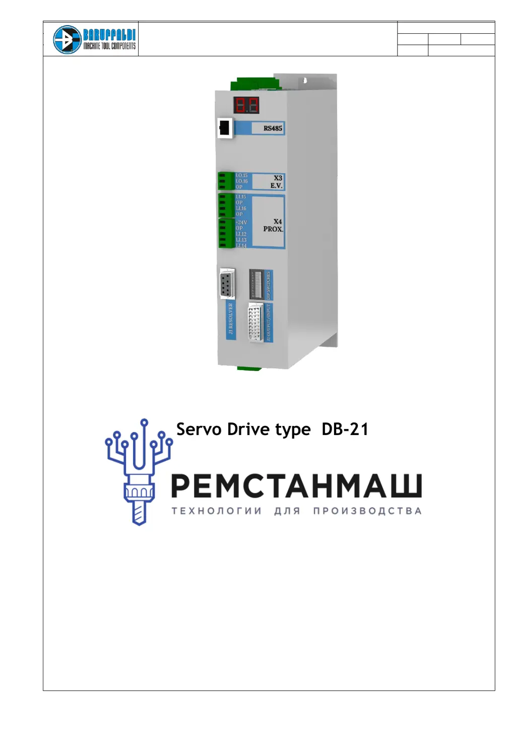
    Why Baruffaldi DB-21 Servo Drives turret is not locked at startup?
    • E
      evan83Sep 6, 2025
      If the Baruffaldi Servo Drives gives a command for locking the turret at startup, and the lock proximity switch (Li.13) is off, the alarm is activated. Check the functionality of the proximity switch, the hydraulic/pneumatic circuit, and the electrovalve/auxiliary relais connection.
  • M
    Matthew KelleyAug 22, 2025
    Why am I getting an overvoltage error on my Baruffaldi Servo Drives?
    • S
      Shawn PadillaAug 22, 2025
      An overvoltage error in Baruffaldi Servo Drives can occur when the input voltage is too high or due to excessive regeneration during braking, causing the bus voltage to rise. Use a multimeter to check the voltage on the L1-L2-L3 connector, ensuring it's within the range of 220V +10%. Also, verify that the inertia and unbalancing applied to the turret do not exceed the stated limits and that the profile selected with the dipswitch is appropriate for the load condition.
  • K
    Kristin JonesSep 3, 2025
    What to do if the Baruffaldi DB-21 Servo Drives turret stays unlocked during locking?
    • R
      rogersjennySep 3, 2025
      If the Baruffaldi Servo Drives turret remains unlocked (Li.12 = On) after 30 seconds from the locking command (Lo.16) and there is no signal from the lock proximity switch (Li.13), check the functionality of the proximity switch. Also, check the hydraulic/pneumatic circuit and the electrovalve/auxiliary relais connection.
  • J
    Jose BrownSep 2, 2025
    What to do if there is no signal from the lock proximity switch on Baruffaldi DB-21?
    • S
      sabrina40Sep 2, 2025
      If there's no signal from the lock proximity switch on Baruffaldi Servo Drives after 30 seconds from the locking command (Lo.16), and the unlock proximity switch is also Off (Li.12), check the functionality of the proximity switch. Remove the upper cover and verify that the movement of the pin is not hindered. Check the hydraulic/pneumatic circuit. Check the turret setup made with the dipswitch and the drive configuration K2/K5.
  • M
    Michael HarrisSep 1, 2025
    What causes undervoltage on Baruffaldi Servo Drives when the turret is unlocked?
    • K
      Kimberly EstradaSep 1, 2025
      Undervoltage on Baruffaldi Servo Drives when the turret is unlocked indicates that the power supply voltage on the M1 connector is less than 80V. Check the voltage on the L1-L2-L3 connector with a multimeter. If the alarm occurs during rotation, the power transformer might not be powerful enough; ensure it is at least 2KVA.
  • E
    Edward RoweAug 30, 2025
    How to resolve a zero search error on Baruffaldi DB-21 Servo Drives?
    • A
      Andrew VincentAug 30, 2025
      This alarm occurs when, at the end of zero search, the turret is locked and the resolver value differs from the value stored during the resolver acquisition sequence. If the turret has reached station N°1, repeat the acquisition of the position resolver. Otherwise, remove the back cover of the turret and, with the turret locked in station N°1, verify that the mechanical position of the zero camshaft matches the picture.
  • M
    Margaret JonesAug 29, 2025
    What does motor PTC alarm mean on Baruffaldi DB-21?
    • M
      michelle05Aug 29, 2025
      The Motor PTC alarm on Baruffaldi Servo Drives activates when continuity is not detected between pin 1 and 2 of J2. This indicates the temperature sensor (PTC) of the motor senses excessive winding temperature. Ensure the ambient temperature near the motor is within allowed limits. If the alarm persists when the motor is cold, check the wires connecting the sensor (pins 1 and 2 of J2 on board and the terminal turret).
  • D
    Derrick SnyderAug 27, 2025
    What to do if Baruffaldi DB-21 calls a non-existing position?
    • T
      Thomas HillAug 27, 2025
      If Baruffaldi Servo Drives requests a position higher than the number of stations provided, check the setting of the dipswitch. Also, check the code management of the position in the PLC, the wiring of connector J1, and reset the drive setup.
  • G
    Gregory TurnerAug 27, 2025
    How to fix resolver malfunctioning on Baruffaldi DB-21 Servo Drives?
    • A
      andersonalexandraAug 27, 2025
      If you encounter a resolver malfunctioning alarm on Baruffaldi Servo Drives, it means the signal from the resolver is either low or absent. Check the wiring of connector J2 and the connections in the terminal block signals on the turret. Inspect the cable for integrity and continuity. Also, ensure that the drive is set to the motor in use.
  • L
    Leah MasseyAug 25, 2025
    Why Baruffaldi DB-21 Servo Drives shows a positioning error?
    • S
      Sandra RogersAug 26, 2025
      A positioning error with Baruffaldi Servo Drives happens at the end of a position inquiry if the turret is locked in a position different from what was expected. The resolver value, based on the acquisition value, differs from the final position resolver. At startup, check that the drive SETUP matches the turret in use (K2/K5/K3). Ensure the dipswitch is properly set according to the turret in use, considering the transmission ratio and number of stations.

Summary

GENERAL WARNINGS

Safety and Operation Precautions

Essential safety warnings and precautions before operating the equipment.

INSTALLATION WARNING

Voltage Setting and Installation

Critical warnings related to voltage settings and correct installation procedures.

SAFETY AND INSTALLATION

SAFETY CONSIDERATION AND INSTALLATION CONSTRAINTS

Guidelines for safe installation, handling of voltages, and proper grounding.

EMC ADVICES

Recommendations for minimizing electromagnetic interference for reliable operation.

SPECIFICATIONS

Technical parameters, limits of use, and physical volume/weight of the servo drive.

ELECTRICAL CONNECTIONS

X1 (INPUT) POWER SUPPLY

Details on connecting the main power supply, including voltage options and protection.

X2 (INPUT) LOGIC SUPPLY

Connection requirements for the logic power supply and its specifications.

X3 (OUTPUT) ELECTROVALVES OUTPUT

Information on the electrovalve outputs for turret control and recommended auxiliary relays.

X4 (OUTPUT) EXTRA PORTS; INDUCTIVE SENSORS

Description of extra ports and connections for inductive sensors used in turret operation.

J2 (INPUT) ANGULAR POSITION TRANSDUCER

Guidelines for connecting the angular position transducer and cable recommendations.

J1 (OUTPUT;INPUT) DIGITALS INPUT;OUTPUT

Pinout and specifications for digital inputs and outputs, including interface with PLCs.

X5 (OUTPUT) MOTOR (U-V-W-T)

Motor connection terminals and cable specifications for driving the servo motor.

DRIVE AND TURRET LAYOUT

Diagram and Connections Overview

Visual representation of the drive and turret layout with key connection points highlighted.

TURRET CONNECTIONS

TB;TBH SERIES (STANDARD ELECTRICAL BOARD ON THE TURRET)

Wiring diagram for TB/TBH series turrets with standard electrical boards.

TB;TBH SERIES (HARTING CONNECTOR)

Wiring diagram for TB/TBH series turrets using Harting connectors.

TAB SERIES (STANDARD ELECTRICAL BOARD ON THE TURRET)

Wiring diagram for TAB series turrets with standard electrical boards.

J1 INPUT;OUTPUT

CONSENT TO WORK

Conditions required for the drive to start operation, based on specific signals.

POSITION FEEDBACK

Explanation of how the drive communicates turret position using binary outputs.

ALARMS

Information on how alarms are communicated and their impact on operation.

START COMMAND

Requirements for the start command timing to ensure proper operation.

OPERATIVE MODE

Description of different operative modes available for the servo drive.

POSITION REQUIRED

Details on setting the required turret position using binary inputs.

DIPSWITCH SETTING (FOR TURRET TYPE SELECTION)

TURRET SELECTION

How to configure the drive for different turret types and positions using dipswitches.

CUSTOM PROFILE

Setting up non-standard applications with custom profiles via software.

DYNAMIC PROFILE

Optimizing drive response based on real load conditions and turret unbalance.

RESOLVER ACQUISITION

Procedure and Sequence

Steps to acquire the resolver value for correct turret positioning.

WORKING LOGIC AND POSITIONING INQUIRY

Start-up and Operation Flow

Step-by-step logic for drive start-up, zero search, and positioning commands.

OPERATIVE MODE

MODE 0 - RESET;EMERGENCY

Mode for resetting alarms, disabling drive, and resetting operational status.

MODE 1 - AUTOMATIC POSITIONING IN THE SHORTEST WAY AND ZERO SEARCH

Default mode for shortest path positioning and performing zero/hidden zero searches.

MODE 2 - AUTOMATIC POSITIONING WITH FORCED CLOCKWISE ROTATION

Positioning mode that forces clockwise rotation regardless of path length.

MODE 3 - AUTOMATIC POSITIONING WITH FORCED COUNTERCLOCKWISE ROTATION

Positioning mode that forces counter-clockwise rotation regardless of path length.

MODE 4 - NEXT;PREVIOUS TOOL REQUEST (JOG MODE)

Mode for manual tool selection and replacement without a program.

MODE 5 - SERVICE MODE

Mode for checking electrovalve system and turret noise during maintenance.

MODE 6 - AUTOTEST

Mode for self-testing the turret functionality without PLC program interaction.

MODE 7 - RESOLVER ACQUISITION

Alternative method for resolver acquisition using operative mode settings.

DRIVE SET-UP (NEW TURRET INSTALLATION)

Sequence of operations N°1 (VOLTAGE SETTING)

Step-by-step procedure for setting the correct input voltage for the drive.

Sequence of operations N° 2 b*

Procedure for selecting turret type, voltage, and number of positions using dipswitches.

DUTY CYCLE (BARUFFALDI LIVE TOOL TOOLING SYSTEM)

Timing and Sequence Diagram

Diagram illustrating the sequence of operations for live tool tooling systems.

DUTY CYCLE (BMT;DIN5480;DIN1809 LIVE TOOL TOOLING SYSTEM)

Timing and Sequence Diagram

Diagram illustrating the sequence of operations for BMT/DIN tooling systems.

DRIVE ALARM

Alarm Codes and Descriptions

Comprehensive list of drive alarms, their codes, descriptions, and impact on operation.

SERVICE

TROUBLESHOOTING

Guide to diagnosing and resolving common drive issues based on display codes and descriptions.

COMPATIBILITY WITH PREVUIOUS VERSIONS

Information on compatibility with older drive and motor models.

DRIVE AND MOTOR TIMELINE

Timeline showing the evolution of drive and motor models.

TURRET SERIAL NUMBER IDENTIFICATION

Method for identifying turret type and model using serial numbers.

DRIVE REPLACEMENT (SET-UP AND SETTING)

Procedure for replacing the drive and setting it up for the specific turret and motor.

MOTOR REPLACEMENT

Step-by-step instructions for replacing the motor on the turret.

RESOLVER ACQUISITION

Procedure for acquiring the resolver position after motor replacement or setup.

ZERO SENSOR SETTING

Steps to set the zero sensor for correct turret homing and positioning.

CABLE ADAPTER FOR OLD DRIVE INTERFACING

Details on using cable adapters for interfacing new drives with older CNC systems.

Baruffaldi DB-21 Specifications

General IconGeneral
BrandBaruffaldi
ModelDB-21
CategoryServo Drives
LanguageEnglish

Related product manuals