J
Jennifer ByrdAug 23, 2025
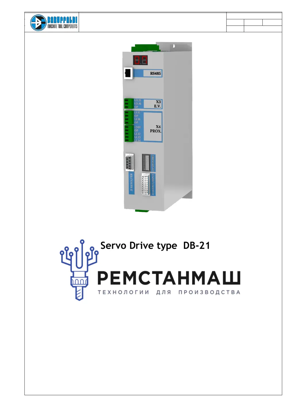
What to do if Baruffaldi DB-21 Servo Drives turret rotation times out?
- TTim HernandezAug 23, 2025
If the Baruffaldi Servo Drives turret does not reach the called position within 60 seconds, it may be due to mechanical interferences preventing rotation. Ensure there are no obstructions. Also, check the wired connections between the drive and turret, specifically M1 UVW and J2.