9492600990 19-19
DECS-150 BESTlogic™Plus
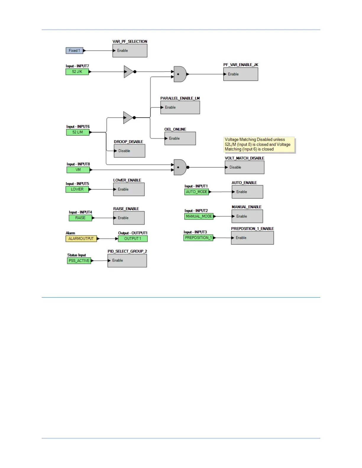
Figure 19-3. PSS-Enabled Default Logic
Programming BESTlogic™Plus
Use BESTCOMSPlus
®
to program BESTlogicPlus. Using BESTlogicPlus is analogous to physically
attaching wire between discrete DECS-150 terminals. To program BESTlogicPlus, use the Settings
Explorer within BESTCOMSPlus to open the BESTlogicPlus Programmable Logic tree branch as shown
in Figure 19-1.
The drag and drop method is used to connect a variable or series of variables to the logic inputs, outputs,
components, and elements. To draw a wire/link from port to port (triangles), click the left mouse button on
a port, pull the wire onto another port, and release the left mouse button. A red port indicates that a
connection to the port is required or missing. A black port indicates that a connection to the port is not
required. Drawing wires/links from input to input or output to output is not allowed. Only one wire/link can
be connected to any one output. If the proximity of the endpoint of the wire/link is not exact, it may attach
to an unintended port.
If an object or element is disabled, it will have a yellow X on it. To enable the element, navigate to the
settings page for that element. A red X indicates that an object or element is not available per the style
number of the DECS-150.
The view of the Main Logic and Physical Outputs can be automatically arranged by clicking the right
mouse button on the window and selecting Auto-Layout.