19-20 9492600990
BESTlogic™Plus DECS-150
The following conditions must be met before BESTCOMSPlus will allow logic to be uploaded to the
DECS-150:
• A minimum of two inputs and a maximum of 32 inputs on any multi-port (AND, OR, NAND, NOR,
XOR, and XNOR) gate.
• A maximum of 24 logic levels for any particular path. A path being an input block or an output side of
an element block through gates to an output block or an input side of an element block. This is to
include any OR gates on the Physical Outputs page, but not the matched pairs of Physical Outputs
blocks.
• A maximum of 256 gates per logic level with a maximum of 125 gates allowed per diagram. All output
blocks and input sides of element blocks are at the maximum logic level of the diagram. All gates are
pushed forward/upwards in logic levels and buffered to reach the final output block or element block if
needed.
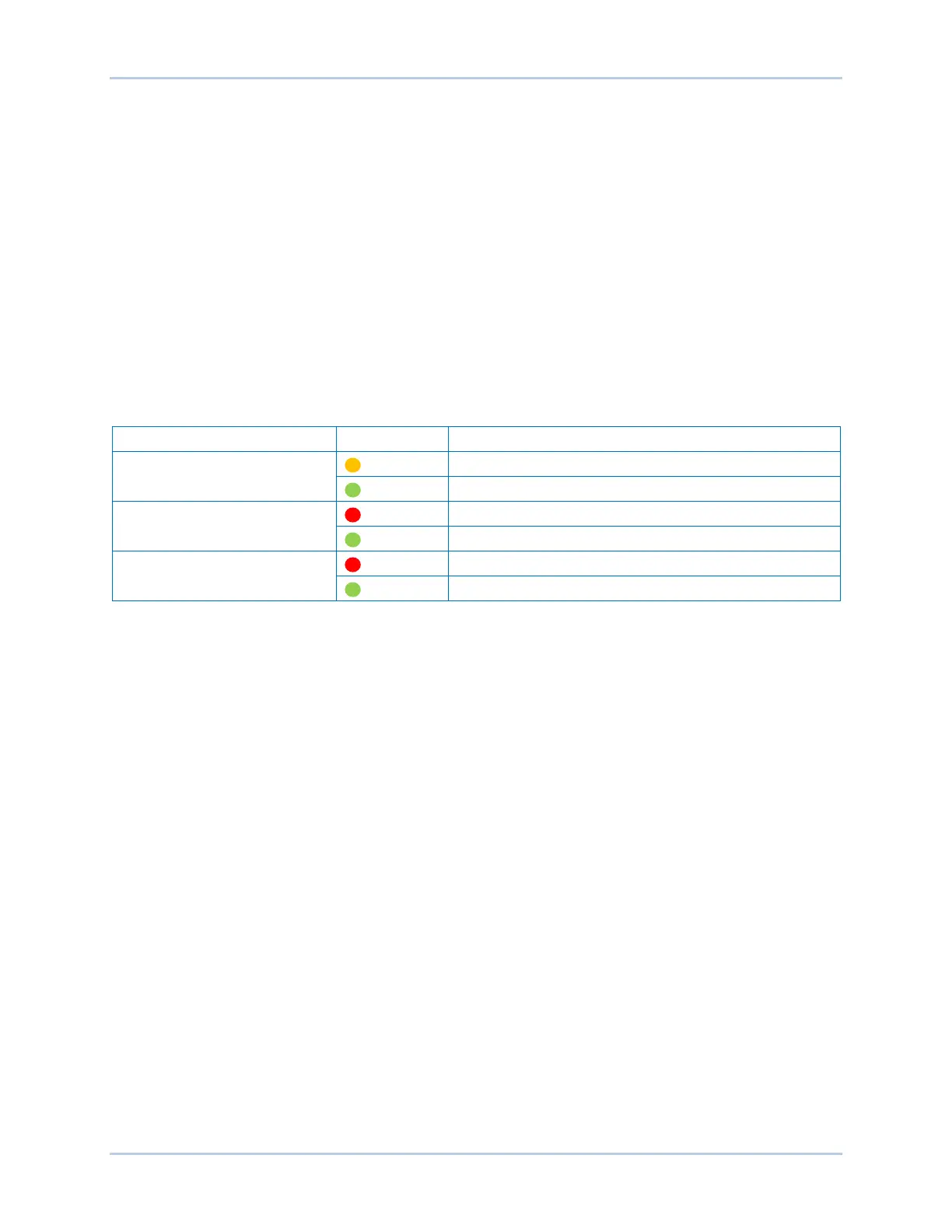
Three status indicators are located in the lower right corner of the BESTlogicPlus window. These
indicators show the Logic Save Status, Logic Diagram Status, and Logic Layer Status. Table 19-4 defines
the colors for each indicator.
Table 19-4. Status Indicators
Indicator Color Definition
Logic Save Status
(Left Indicator)
Logic has changed since last save.
Green Logic has NOT changed since last save.
Logic Diagram Status
(Center Indicator)
Red Requirements NOT met as listed above.
Requirements met as listed above.
Logic Layer Status
(Right Indicator)
Red Requirements NOT met as listed above.
Green Requirements met as listed above.
Pickup and Dropout Timers
A pickup timer produces a true output when the elapsed time is greater than or equal to the Pickup Time
setting after a false to true transition occurs on the Initiate input from the connected logic. Whenever the
Initiate input status transitions to false, the output transitions to false immediately.
A drop out timer produces a true output when the elapsed time is greater than or equal to the Dropout
Time setting after a true to false transition occurs on the Initiate input from the connected logic. Whenever
the Initiate input transitions to true, the output transitions to false immediately. Refer to Figure 19-4.
To program logic timer settings, use the Settings Explorer within BESTCOMSPlus
®
to open the
BESTlogicPlus Programmable Logic/Logic Timers tree branch. Enter a Name label that you want to
appear on the timer logic block. The Time Delay value range is 0 to 250 hours in 1 hour increments, 0 to
250 minutes in 1 minute increments, or 0 to 1,800 seconds in 0.1 second increments.
Next, open the Components tab inside the BESTlogicPlus window and drag a timer onto the program
grid. Right click on the timer to select the timer you want to use that was previously set on the Logic
Timers tree branch. The Logic Timer Properties Dialog Box will appear. Select the timer you want to use.
Timing accuracy is ±15 milliseconds.