9492600990 19-23
DECS-150 BESTlogic™Plus
Clearing the On-Screen Logic Diagram
Click on the Clear button to clear the on-screen logic diagram and start over.
BESTlogic™Plus Examples
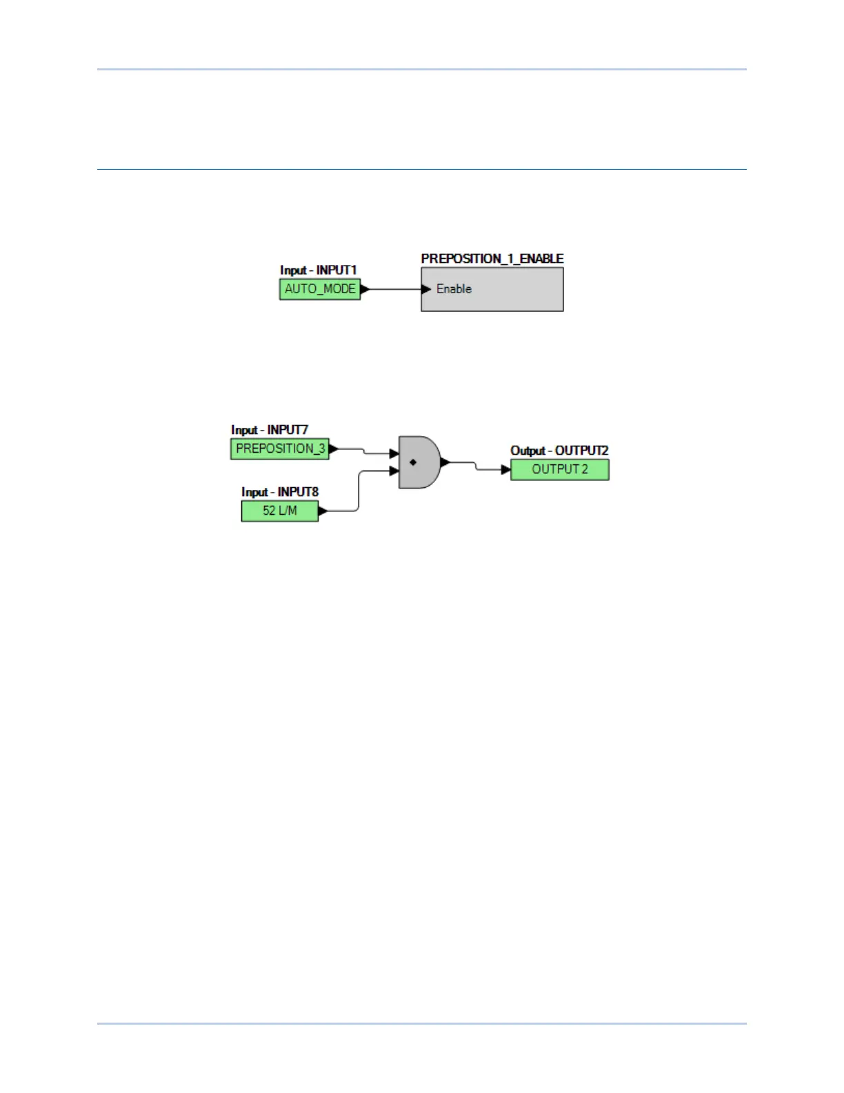
Example 1 - PREPOSITION_1_ENABLE Logic Block Connections
Figure 19-7 illustrates the PREPOSITION_1_ENABLE logic block and one input logic block. Pre-Position
1 is enabled when Input 1 is active.
Figure 19-7. Example 1 - PREPOSITION_1_ENABLE Logic Block Connections
Example 2 - AND Gate Connections
Figure 19-8 illustrates a typical AND gate connection. In this example, Output 2 will become active when
Inputs 7 and 8 are true.
Figure 19-8. Example 2 - AND Gate Connections