9492600990 5-3
DECS-150 Regulation
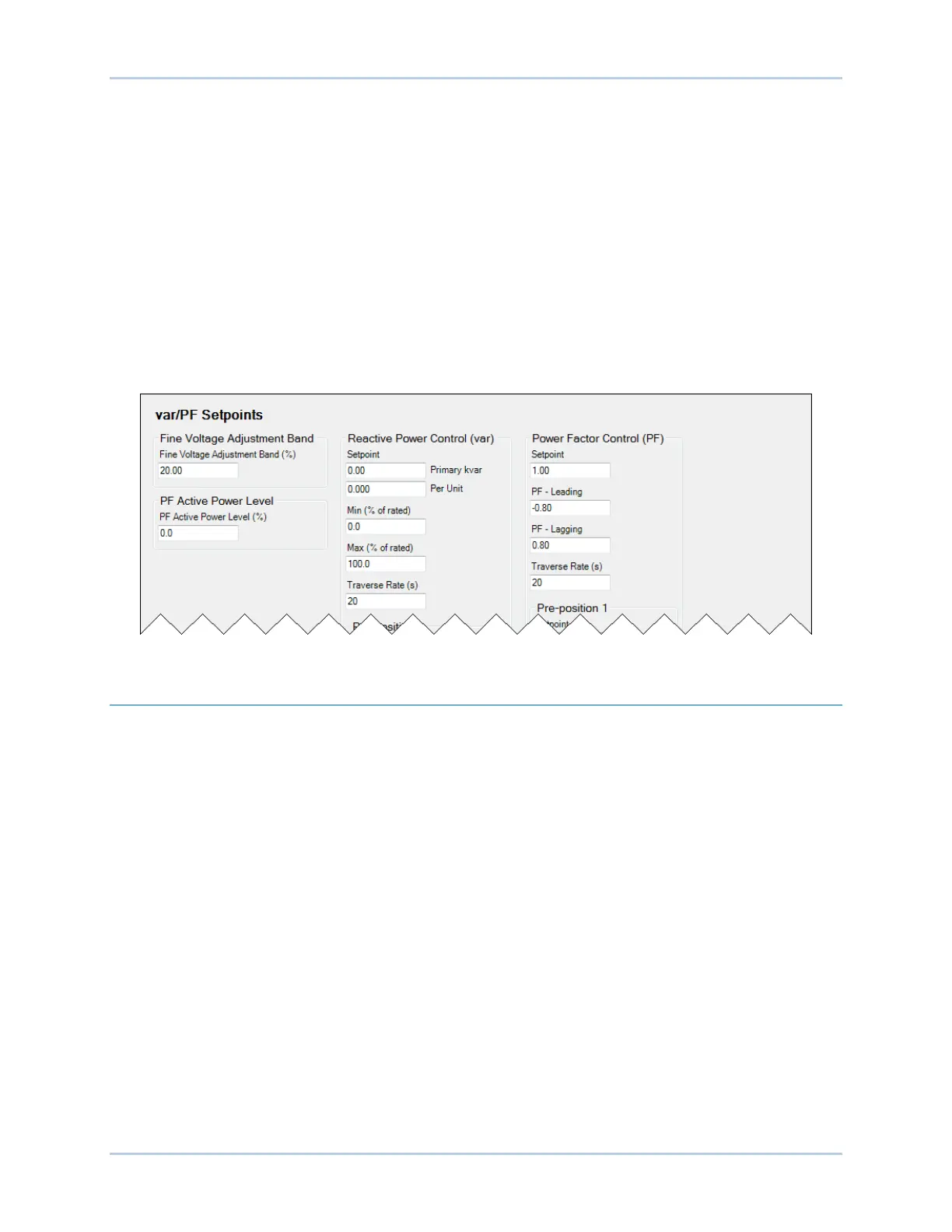
The var/PF Setpoints screen is illustrated in Figure 5-2.
Power Factor
When operating in Power Factor (PF) mode, the DECS-150 controls the var output of the machine to
maintain the Power Factor setpoint as the kW load on the machine varies. The setting range of the PF
setpoint is determined by the PF – Leading and PF – Lagging settings. The length of time required to
adjust the PF setpoint from one limit to the other is controlled by a Traverse Rate setting. A Fine Voltage
Adjustment Band setting defines the upper and lower boundaries of voltage correction when the DECS-
150 is operating in var or Power Factor regulation modes. PF Active Power Level establishes the level of
machine output power (kW) where the DECS-150 switches to/from Droop Compensation/Power Factor
mode. If the level of power decreases below the setting, the DECS-150 switches from Power Factor mode
to Droop Compensation mode. Conversely, as the level of power increases above the setting, the DECS-
150 switches from Droop Compensation mode to Power Factor mode. A setting of 0 to 30% may be
entered in 0.1% increments.
The var/PF Setpoints screen is illustrated in Figure 5-2.
Figure 5-2. Var/PF Setpoints Screen
Pre-Position Setpoints
Each regulation mode has three pre-position setpoints that allow the DECS-150 to be configured for
multiple system and application needs. Each pre-position setpoint can be assigned to a programmable
contact input. When the appropriate contact input is closed, the setpoint is driven to the corresponding
pre-position value.
Each pre-position function has three settings: Setpoint, Traverse Rate, and Mode. The setting range of
each pre-position setpoint is identical to that of the corresponding control mode setpoint. The length of
time required to adjust from one pre-position setpoint to another is controlled by the Traverse Rate
setting. A setting of zero (0) implements an instantaneous step.
Mode
The Mode setting determines whether or not the DECS-150 will respond to further setpoint change
commands while the pre-position command is being asserted. If the pre-position mode is Release,
setpoint change commands are accepted to raise and lower the setpoint while the pre-position command
is being asserted. Additionally, if the inactive pre-position mode is Release and internal tracking is
enabled, the pre-position value will respond to the tracking function. If the pre-position mode is Maintain,
further setpoint change commands are ignored while the appropriate contact input is closed. Additionally,
if the inactive pre-position mode is Maintain and internal tracking is enabled, the inactive mode will
maintain the inactive setpoint at the pre-position value and override the tracking function.
A portion of the pre-position setpoints for var and PF modes are illustrated in Figure 5-3. (Pre-Position
Setpoints for AVR and FCR modes are similar and not shown here.)