5-4 9492600990
Regulation DECS-150
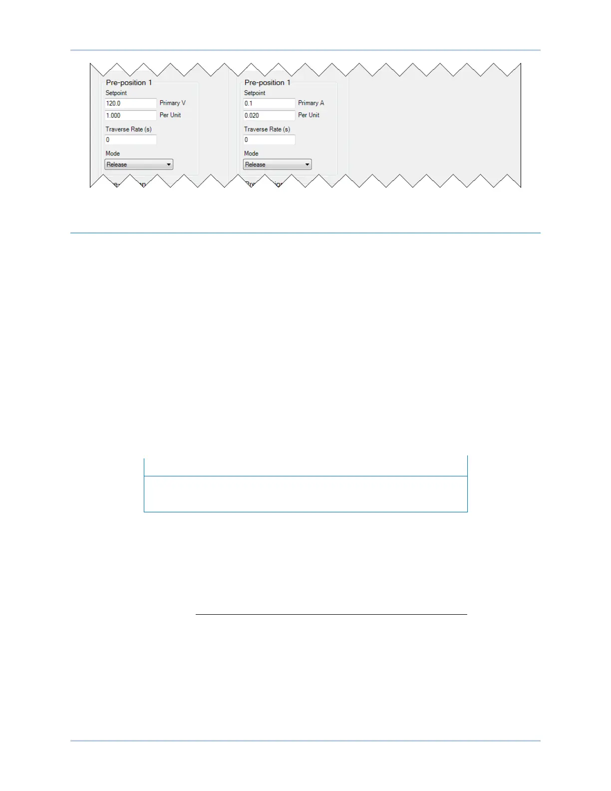
Figure 5-3. Pre-Position Setpoints
Operation with Paralleled Generators
BESTCOMSPlus Navigation Path: Settings Explorer, Operating Settings, Parallel/Line Drop
Compensation
The DECS-150 can be used to control the excitation level of two or more generators operating in parallel
so that the generators share the reactive load. The DECS-150 can employ either droop compensation or
cross-current compensation (reactive differential) schemes for reactive load sharing.
The Parallel/Line Drop Compensation screen is illustrated in Figure 5-4.
Droop Compensation
Droop compensation serves as a method of controlling reactive current when the generator is connected
in parallel with another energy source. Droop compensation utilizes the B-phase CT. When droop
compensation is enabled, the generator voltage is adjusted in proportion to the measured generator
reactive power. The reactive droop compensation setting is expressed as a percentage of the generator
rated terminal voltage.
By default logic, closing Contact Input 6 (52 L/M) disables parallel operation. An open contact enables
parallel operation and the DECS-150 operates in reactive droop compensation mode.
For droop compensation to operate, the PARALLEL_EN_LM logic
block must be set true in BESTlogicPlus programmable logic.
Line Drop Compensation
When enabled, line drop compensation can be used to maintain voltage at a load located at a distance
from the generator. The DECS-150 achieves this by measuring the line current and calculating the
voltage for a specific point on the line. Line drop compensation is applied to both the real and reactive
portion of the generator line current. It is expressed as a percentage of the generator terminal voltage.
Equation 5-1 is used to calculate the Line Drop Value.
=
×
× cos
+ ×
× sin
Equation 5-1. Line Drop Value
LD
Value
= Line drop value (per unit)
V
avg
= Average voltage, metered value (per unit)
LD = Line Drop % / 100
I
avg
= Average Current, metered value (per unit)
I
bang
= Angle of phase B current (no compensation)