9492600990 11-5
DECS-150 Metering
Figure 11-9. Auxiliary Control Input Metering
Tracking
BESTCOMSPlus Navigation Path: Metering Explorer, Tracking
The metered setpoint tracking error between DECS-150 operating modes is displayed on the Tracking
screen (Figure 11-10). Status fields are also provided for the on/off status for internal and external
setpoint tracking. An additional status field indicates when the setpoint of an inactive operating mode
matches the metered value.
Figure 11-10. Tracking Metering
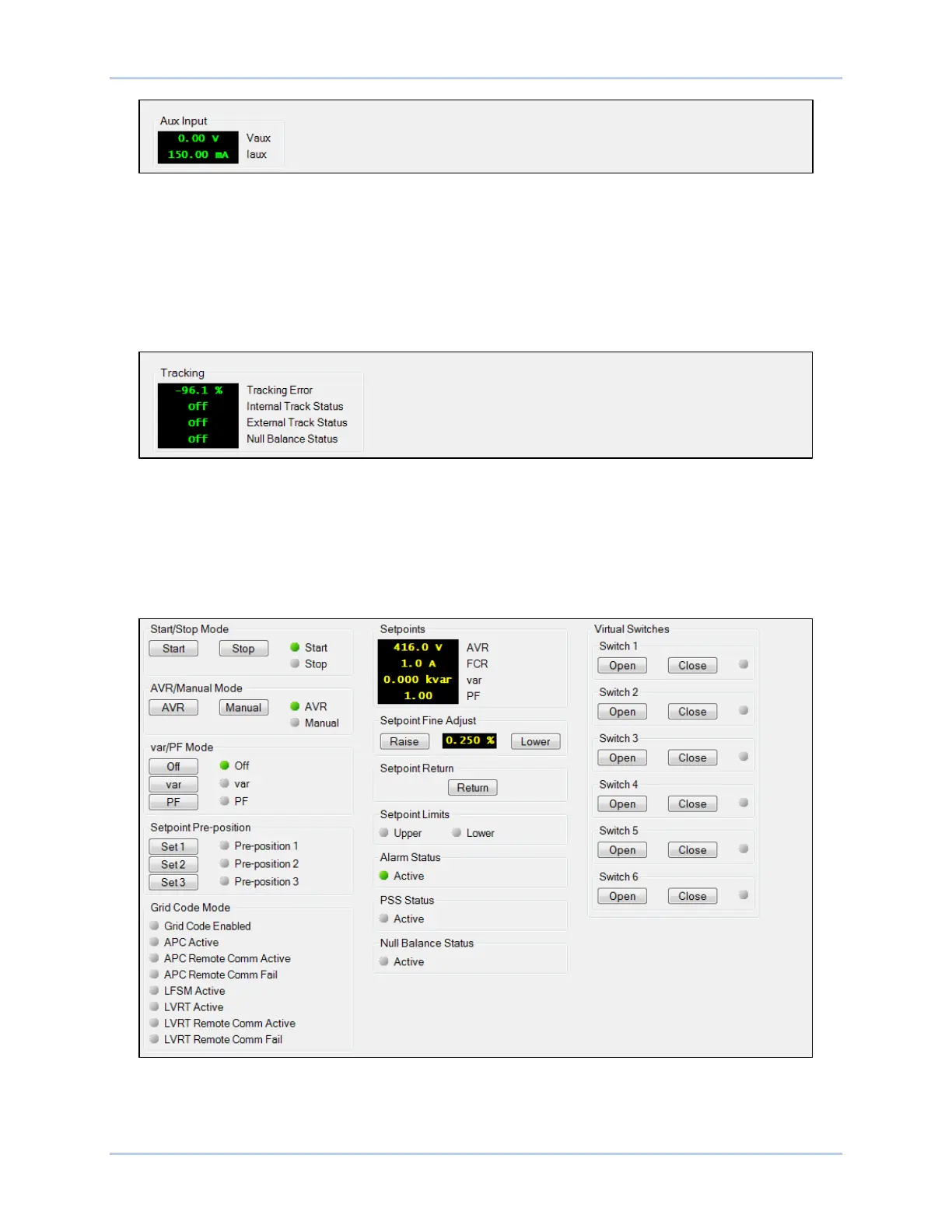
Control Panel
BESTCOMSPlus Navigation Path: Metering Explorer, Control Panel
The Control Panel (Figure 11-11) provides options for changing operating modes, selecting setpoint pre-
positions, fine tuning setpoints, and toggling virtual switches. The setpoints for AVR, var, and PF are
displayed, as well as Alarm status, PSS status, Null Balance status, and Grid Code Mode.
Figure 11-11. Control Panel
Start/Stop Mode: Two indicators show the start/stop mode of the DECS-150. When a mode is active, its
corresponding indicator changes from gray to green. To select the DECS-150 Start status, click the Start
button. Click the Stop button to select DECS-150 Stop status.