Home
Baumuller
Controller
BUS 6 VC
Page 22 (LED Display Element)
Baumuller BUS 6 VC - LED Display Element
110 pages
Manual
Save Page as PDF
To Next Page
To Next Page
To Previous Page
To Previous Page
Loading...
Installation
20
V-Controller (BUS 6 VC)
5.03047.01
Baumüller Nürnberg Elec
tronic GmbH & Co.
KG
5.3.2
LED Display E
lement
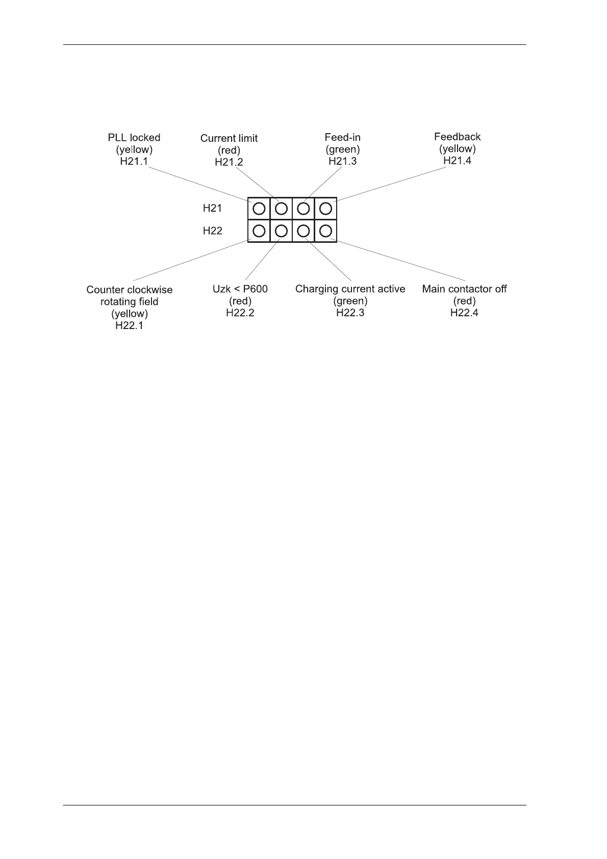
An LED display, which giv
es additional inform
ation, is located below
the 7-segment display.
see function
module LED d
isplay
21
23
Table of Contents
Main Page
Default Chapter
5
Table of Contents
5
1 Safety Information
9
2 Technical Data
11
General
11
Electrical Data
12
Type Code
13
3 Transportation, Unpacking
15
4 Assembly
17
Dimensions
17
Assembly Note
18
5 Installation
19
Danger Information
19
Checks Prior to Installation
20
Display
21
Seven-Segment Display
21
LED Display Element
22
Terminal Diagram V-Controller (Version: Digital Controlled BUC)
23
Connection of the Function Inputs
24
Connector Pin Assignment
25
Connection Cables
27
Serial Connection Cable for PC
27
Accessories
28
6 Commissioning
29
Danger Information
29
Initial Commissioning of V-Controller
32
7 Parameters
33
Function Diagrams
33
Power Unit
35
Overload Monitoring of Power Unit
39
Pulse Width Modulation
42
Current Controller
44
Uzk Controller (Uzk Value Setting)
47
Drive Manager (Enable the Controller)
49
New BUC Parameter
57
Data Set Management
61
Operation System
67
Ramp Function Generator
69
Set Value Generator
73
Analog Inputs
75
Analog Outputs
80
Digital Inputs
82
Digital Outputs
86
Service Interface
88
8 Maintenance
93
Maintenance Information
93
Error Messages
94
Disposal
98
9 Appendix
99
Declaration by Manufacturer
99
General Conditions of Sale and Delivery
100
Parameter List
103
Index
107
Related product manuals
Baumuller b Maxx Series
82 pages
Baumuller b maXX BM5800
816 pages