The pipes must deliver a maximum pressure drop in compliance with the
values given in the table below.
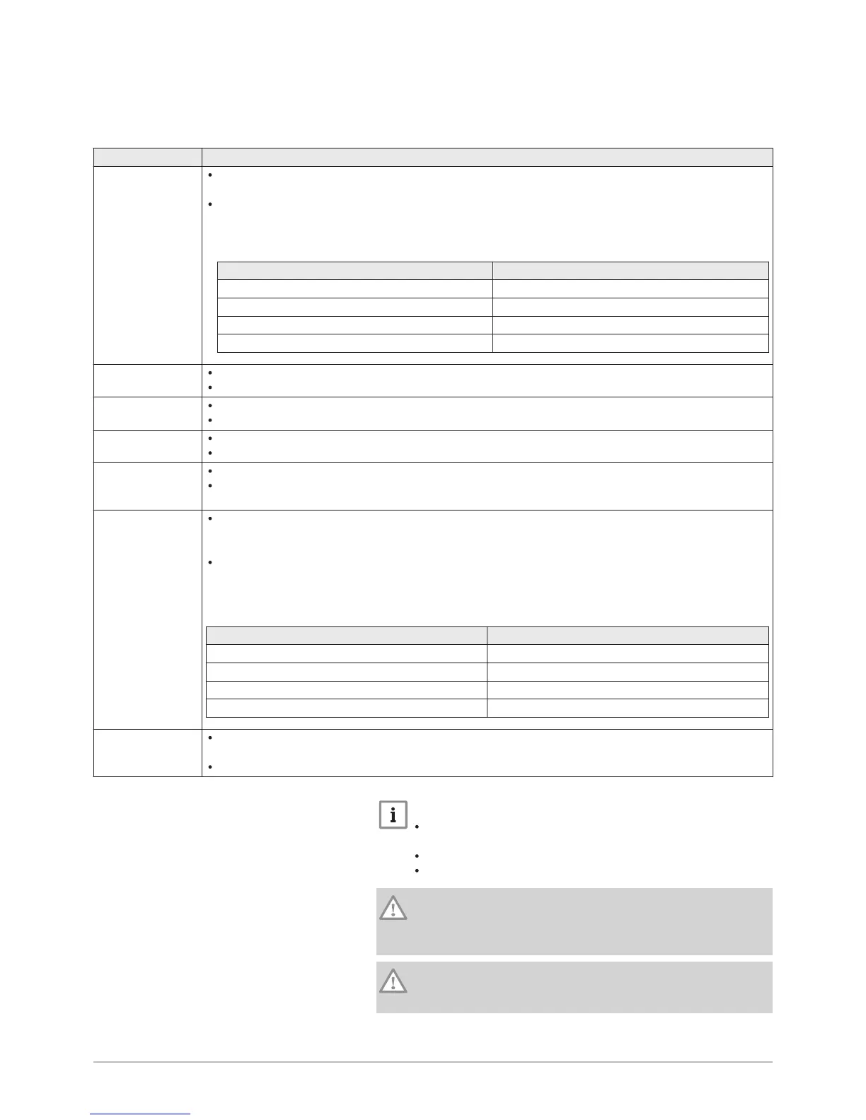
Tab.17 Configurations and recommendations for the flue system
Configuration Description
B
23
– B
23P
Connection to a chimney using a connection kit (single pipe in a flue, combustion air taken from the boil
er room).
The maximum pressure drop in the pipes ΔP must not exceed the values given in the table below. The
pipes must be certified for this type of use and for a temperature in excess of 100°C.
Tab.18
Model Maximum pressure drop ΔP (Pa)
POWER HT+ 1.130 200
POWER HT+ 1.150 200
POWER HT+ 1.200 200
POWER HT+ 1.250 200
C
13
Air/flue gas connection using concentric pipes to a horizontal terminal (so-called forced flue).
The terminal parts of the singled-up discharge pipe must be scheduled inside a 50 cm square.
C
33
Air/flue gas connection using concentric pipes to a vertical terminal (roof outlet).
The terminal parts of the singled-up discharge pipe must be scheduled inside a 50 cm square.
C
43
Air/flue gas connection to a collective flue for sealed boilers.
The chimney or flue gas pipe must be suitable for such use.
C
53
Separate air/flue gas connection using a bi-flow adapter.
The terminal parts of combustion air intake and combustion product discharge pipes must not be plan
ned on opposite walls of the building.
C
63
The maximum pressure drop in the pipes ΔP must not exceed the values given in the table below. The
pipes must be certified for this type of use and for a temperature of more than 100 °C. The terminal part
of the flue gas pipe must be certified as complying with the EN 1856-1 Standard.
If installing discharge and intake pipes not supplied by Baxi, these must be certified for the type of use
scheduled and present a maximum pressure drop in line with the values given in the table below.
Tab.19
Model Maximum pressure drop ΔP (Pa)
POWER HT+ 1.130 170
POWER HT+ 1.150 280
POWER HT+ 1.200 230
POWER HT+ 1.250 230
C
83
Flue gas connection to a collective flue for sealed boilers. The air supply is individual via a terminal
coming from outside the building.
The chimney or flue gas pipe must be suitable for such use.
Important
Only original components are authorised for connection to the
boiler and for the terminal.
The clear section must comply with the standard.
The chimney must be swept before installing the discharge flue.
Caution
Ensure that the flue gas discharge pipes are securely attached to
the wall with suitable retaining flanges to prevent any damage and
guarantee the tightness of every gasket in the circuit.
Caution
The minimum gradient of the condensates discharge pipe from the
boiler to the waste water discharge must be 1 cm per linear metre.
7 Installation

 Loading...


