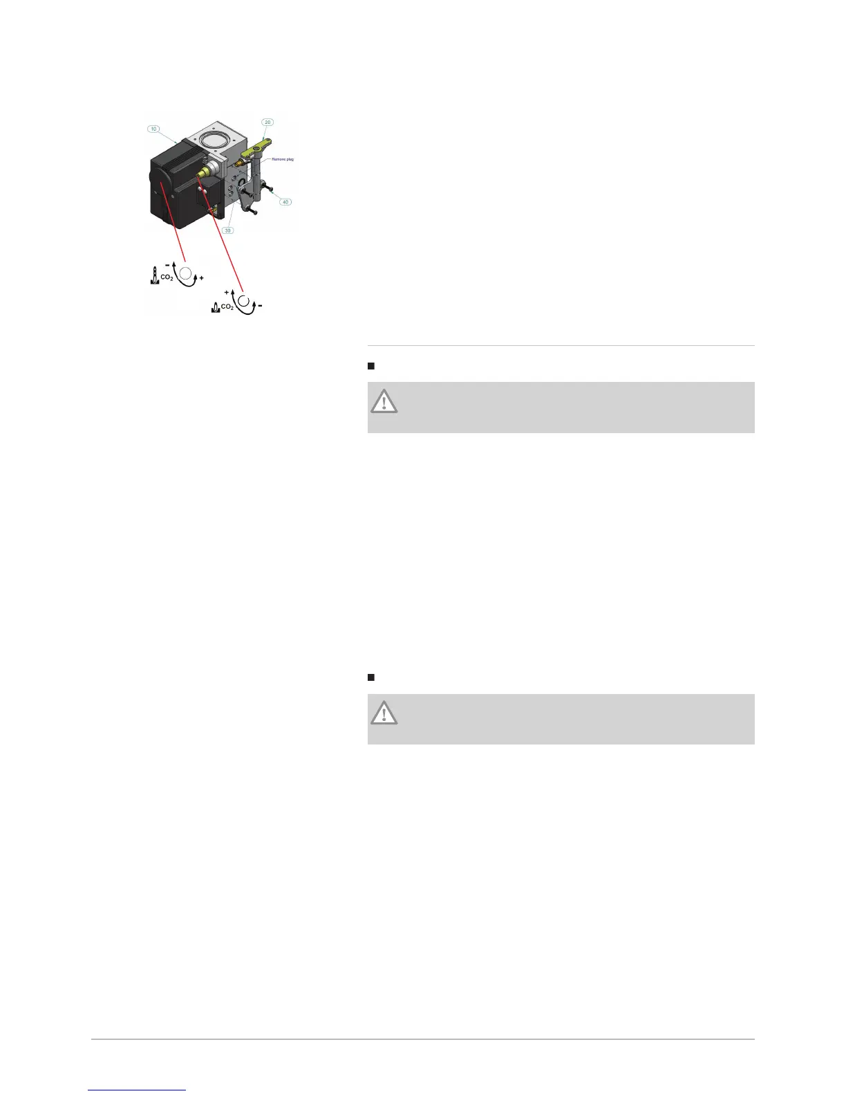
1 Gas flow rate setting screw
The settings screw is screwed down as far as it will go and is then
unscrewed according to the number of turns given in the above
table.
2 OFFSET setting screw:
1
.
Remove the protective cap.
2
.
Use an Allen key.
3 The settings screw is screwed down as far as it will go and is then
unscrewed according to the number of turns given in the above
table.
4 Put the cap back in place.
8.4.5 Conversion to propane (G31)
POWER HT+ 1.130 and POWER HT+ 1.150
Caution
Only a fully trained, qualified professional may carry out the
following operations.
The boiler is pre-set in the factory to run on natural gas H (G20).
Adaptation kits are available for propane (G31).
1. Close the mains gas valve.
2. Disconnect the gas valve electrical connection.
3. Remove the two nuts from the flange under the gas valve.
4. Remove the 4 screws from the flange connecting the gas valve to the
venturi.
5. Take out the gas valve.
6. Integrate the restrictor provided for the required gas on the gas valve
outlet.
7. Replace the O-ring.
8. Proceed to refit the valve by reversing the steps above.
9. Check the tightness using a leak detector spray.
10. Replace the gas setting label with the one delivered with the boiler
and tick the corresponding gas setting.
POWER HT+ 1.200 and POWER HT+ 1.250
Caution
Only a fully trained, qualified professional may carry out the
following operations.
The boiler is pre-set in the factory to run on natural gas H (G20).
Adaptation kits are available for propane (G31).
1. Close the mains gas valve.
2. Disconnect the gas valve electrical connection.
3. Remove the 8 screws from the elbow connecting the gas valve to the
venturi (4 screws per flange).
4. Remove the elbow.
5. Integrate the restrictor provided for the required gas on the gas valve
outlet.
6. Change the O-rings.
7. Proceed to refit the elbow by reversing the steps above.
8. Check the tightness using a leak detector spray.
9. Replace the gas setting label with the one delivered with the boiler
and tick the corresponding gas setting.
Fig.97 Gas valve for POWER HT+ 1.200
and POWER HT+ 1.250

 Loading...


