Device Description
Frost protection device When the flow temperature is lower than 5 °C, the burner starts up and runs until the
flow temperature reaches 15 °C. This device runs under the following conditions:
The boiler is switched on
The gas supply is working
The pressure in the system is higher than 0.5 bar (0.05 MPa)
Anti-blocking of the pump If there are no heating or domestic hot water requirements for 24 consecutive hours, the
pumps start up automatically and run for 10 seconds.
The pumps connected directly to the appliance's terminal blocks are started up every
Friday at 10:00 a.m. and run for 30 seconds.
Anticipatory start-up of the circulat
ing pumps
In heating mode only, the appliance can start up the circulating pumps before burner ig
nition. The duration and activation of anticipatory start-up depends on the installation re
quirements and the operating temperatures. The duration of anticipatory start-up of the
circulating pumps therefore varies from a few seconds to several minutes.
Flue gas pressure switch The flue gas pressure switch interrupts the intake of gas to the burner in the event of a
blockage in the discharge pipe for the combustion products or the combustion air inlet
pipe.
4.3
Main components
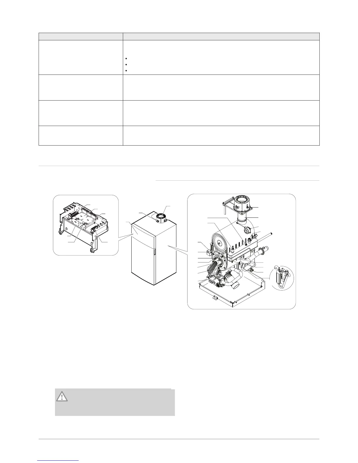
4.3.1 POWER HT+ 1.130 and POWER HT+ 1.150
Fig.11
1 Control panel
2 Flue gas connection
3 Flue gas measuring point
4 Controller PCB
5 Mounting point for a maximum of two AVS 75
modules. A third AVS 75 module can be used by the
boiler but must be fixed to the wall and powered
externally.
6 Power supply terminal block
7 Terminal block for the sensors and the remote
control
8 Mounting point for communication module OCI 345
Caution
Danger of short circuit on the OCI 345
communication module if it is fixed in another
emplacement.
9 Mounting point for conversion module AGU 2.551
10 Gas valve
11 Ionisation probe
12 Burner
13 Ignition electrode
14 Flame inspection window
15 Safety thermostat on the combustion chamber door
16 Ignition transformer
17 Hydraulic pressure sensor
18 Return temperature sensor
19 Flue gas sensor
20 Flue gas fitting
21 Flue gas pressure switch
22 Automatic air vent
23 Safety thermostat
24 Flow temperature sensor
25 Drain valve
26 Condensate siphon
4 Description of the product
 Loading...


