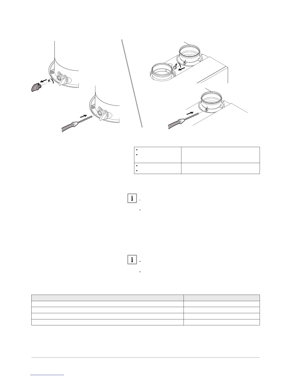
7. Unscrew:
POWER HT+ 1.130
POWER HT+ 1.150
the left-hand plug, which corresponds to
the flue gas measurement point connec
tion.
POWER HT+ 1.200
POWER HT+ 1.250
the plug for the rear nozzle.
8. Connect the flue gas analyser to the measurement point.
Important
Ensure that the opening around the sensor is completely sealed
when taking measurements.
POWER HT+ 1.130 and POWER HT+ 1.150: Insert the sensor
into the flue gas measurement point to at least 8 cm.
9. Set the boiler's heat input to 100% at full load.
10. Measure the percentage of CO
2
in the flue gases.
11. Compare the values measured with the set point values in the Control
and setting values table.
12. If necessary, adjust the air/gas ratio using the gas flow rate
adjustment screw.
Important
Turn the gas adjustment screw clockwise to reduce the CO
2
content.
Turn the gas adjustment screw counter-clockwise to increase
the CO
2
content.
Tab.31 Checking and setting values for gas type G20 / G25 / G25.1 / G27 / G31
Boiler model Maximum CO (ppm)
POWER HT+ 1.130 < 250
POWER HT+ 1.150 < 250
POWER HT+ 1.200 < 250
POWER HT+ 1.250 < 250
Fig.92

 Loading...


