7
QUICK SET UP GUIDE
Locate the four bolt holes on each side of each hub.
Some hubs may have spacer boards mounted to the sides;
these prevent gaps between cabinets.
Open all front doors and remove back doors to access the
inside of the cabinets.
Attach the hubs in the desired order with the included bolts,
washers and lock nuts.
Use a 1/2” socket to tighten the bolts securely.
x4
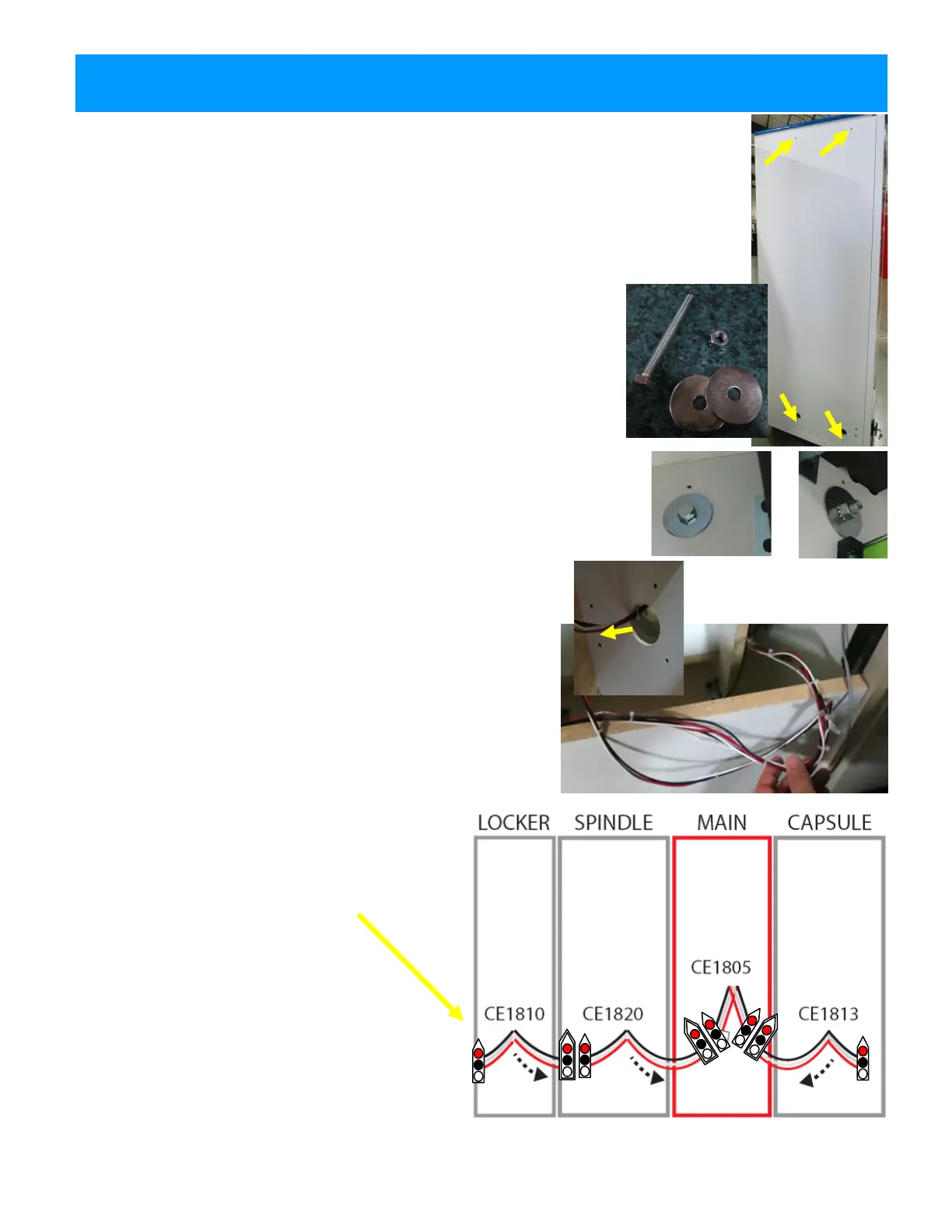
Feed the loose connector ends of the red, black and white
power cables (connected to the control board of each hub)
through the large holes near the floor of the cabinets.
Link to the adjoining hubs, going from the outside hubs
toward the Main hub. There are two connector ends on
each cable; the outermost cabinets will only use one.
The power cables are numbered as follows:
Spindle Hub: CE1820
Capsule Hub: CE1813
Locker Hub: CE1810
Plug the two final ends into the CE1805 cable
inside the Main hub.
Power cable diagram is viewed from the back
of game.
 Loading...