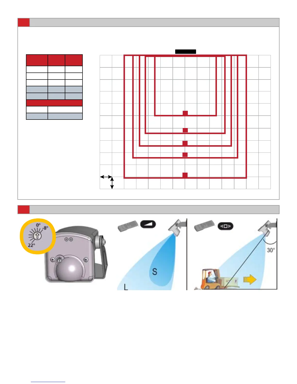
9
12”
A
B
C
D
E
10
0-9
1-6
* Dimensions are approximate
.
Approximate default IR pattern size using a 15º sensor tilt angle.
The higher the mounting height the larger the IR pattern.
SENSOR
IR PATTERN SIZE AT 15° SENSOR ANGLE
Page 4 of 9 75.5695.01 EN 20120113
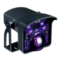
MICROWAVE FIELD ADJUSTMENTS
Adjust the Microwave eld
size.
Refer to page 5.
Choose the correct rejection
mode for your application.
Refer to page 6.
By turning this dial, the radar eld
angle is reduced or increased (from
-8° to +22°).
Refer to page 5.
Mounting
Height
Width * Depth *
A = 8 ft 5 ft 5 ft
B = 10 ft 7 ft 7 ft
C = 11.5 ft 7.5 ft 7.5 ft
D = 13 ft 8.5 ft 8.5 ft
E = 16 ft 10 ft 10 ft
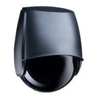
Maximum Mounting Height
IS40XL 11. 5 ft
IS40 16 ft
Use of BEA Spotnder may be
utilized to locate IR eld.