8
7
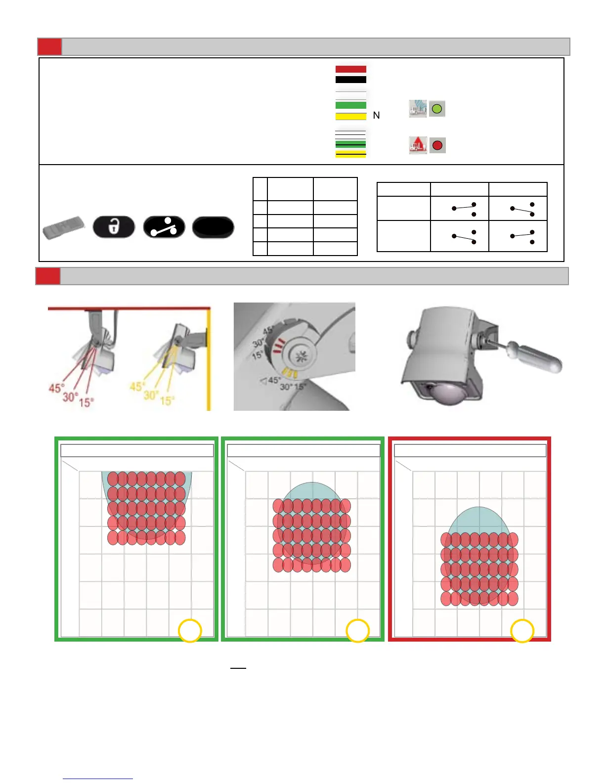
WIRING AND RELAY CONFIGURATION
Notes:
1. It is important to adjust sensor angle rst to position IR eld correctly. Next adapt angle of radar eld as
shown in step 10 by using tilt angle adjustment screw.
2. To obtain an IR pattern that’s straight down (closest to the door threshold); wall mounted sensors need to be
set at 20º; sensors mounted on an extension bracket or out from the wall should be set to approximately 15º.
3. The graphics above are not to scale and for illustration purposes and represent an approximate IR detection
field when at 16 ft. The point of emphasis is to show the IR detection area with respect to the sensor angles.
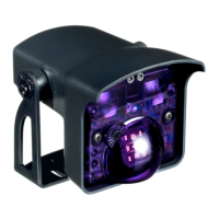
SENSOR ANGLE
COM
NO
NC
RED
BLACK
12-24 V
AC-DC
WHITE
GREEN
YELLOW
WHITE/BLACK
GREEN/BLACK
YELLOW/BLACK
COM
NO
NC
Green LED
Motion
Red LED
Presence
1-4
Activation
Relay
Presence
Relay
1 Active Passive
2 Passive Active
3 Passive Passive
4 Active Active
Description Active Passive
Detection
COM COM
No
Detection
COM COM
NO
NC
NO
NC
NO
NC
NO
NC
RELAY
CONFIGURATION
WIRING
75.5695.01 EN 20120113 Page 3 of 9
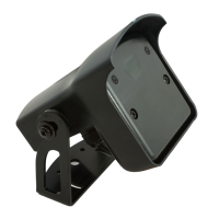
Adjust the angle of the sensor to position the detection elds.
Tighten the screws rmly.
RECOMMENDED
SPECIAL APPLICATIONS
CEILING
WALL
15°
30°
45°
ACTIVATION RELAY
PRESENCE RELAY
POWER
RECOMMENDED