75.5753.15 LZR-MICROSCAN T 20180720 Page 5 of 16
1 2 3
64 5
7 8
75.5753.15 LZR-MICROSCAN T 20180720 Page 5 of 16
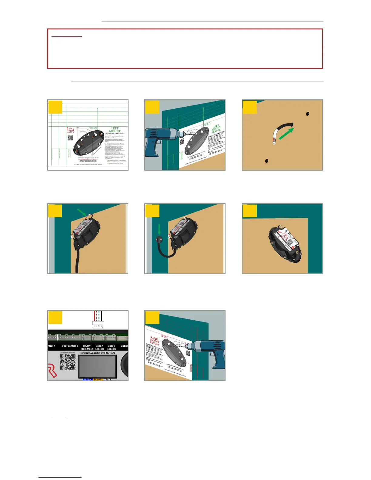
INSTALLATION
Sensors
Use Mounting Template to
position each sensor correctly.
Check for obstructions/clearance.
Align Mounting Template, and
then mark and drill holes.
1
Repeat
on both sides of door. Be sure to
drill the correct size holes.
Run Slave Sensor Harness through
door.
Nominal slave-sensor harness function
hole is typically Ø
1
⁄2" or less.
Using instructions on Mounting
Template, mount MASTER sensors
with appropriate screws. Plug in
Slave Sensor Harness at the upper
most port on sensor.
Using instructions on Mounting
Template, mount SLAVE sensors
with appropriate screws. Plug in
Slave Sensor Harness at the upper
most port on sensor.
Install Door Loop: Drill
1
⁄2” passage
hole in header and jamb, then
route Master Sensor Harness, and
install the cap.
Plug Master Sensor Harness into
hub port labeled Door A Sensors
If necessary, repeat steps 1 – 7 for
second door leaf using hub port
Door B Sensors.
IMPORTANT:
• Refer to mounting template for full mounting instructions!
• Mounting height of 75” (min) to 98” (max) from finished floor to sensor LED.
• Function holes must not be more than Ø 1".
NOTES:
1. Spacer required for applications with door hardware extending across width of door.
Do not apply sensor covers until system is fully operational. Do not adjust tilt angle.