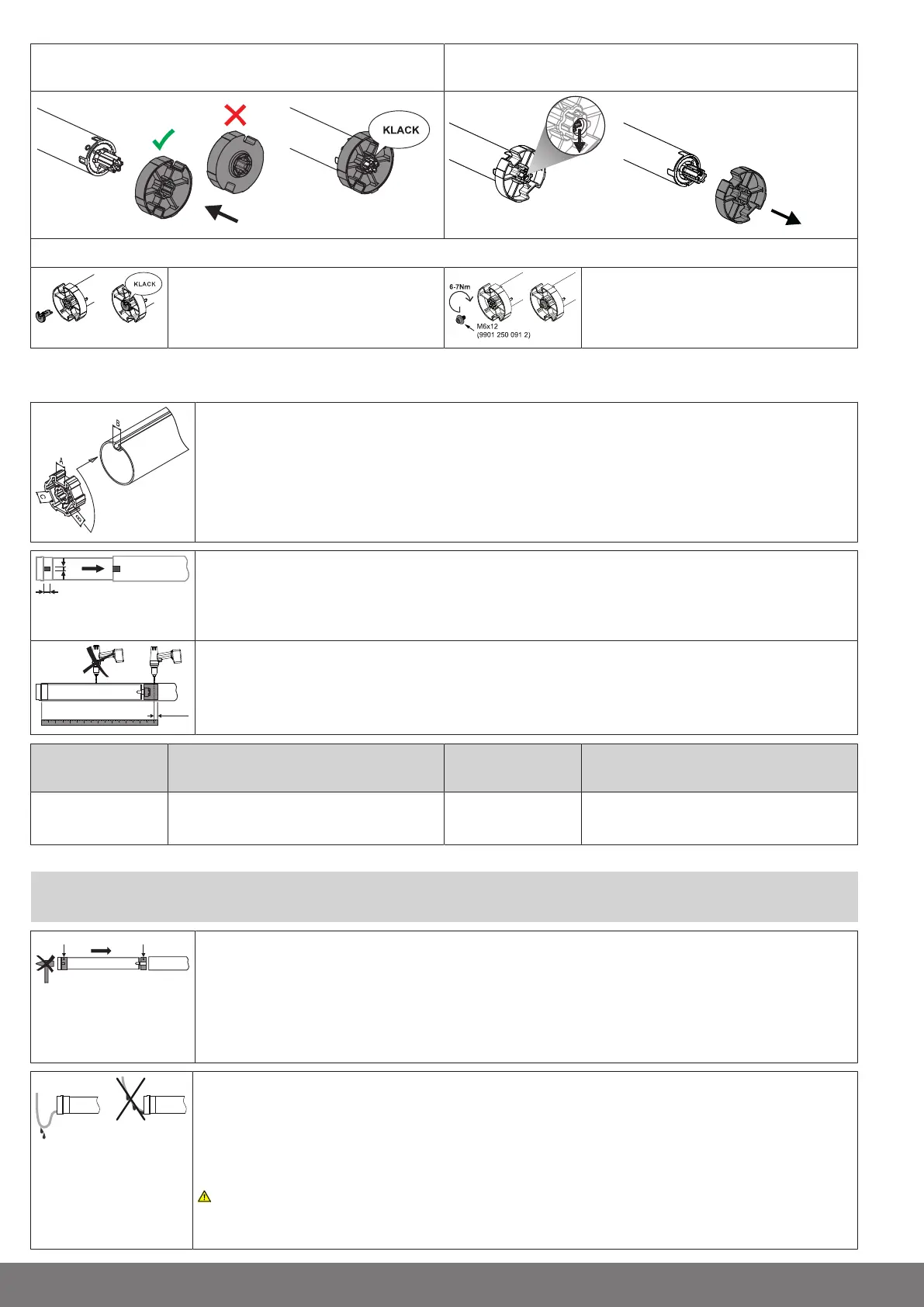
Assembling the drive adapter with safety catch on the
drive shaft
Disassembling the drive adapter with safety catch on the
drive shaft
Assembling and disassembling the drive adapter with drive adapter safety catch or screw connection
Assembling and disassembling the drive
adapter with separate drive adapter
safety catch
Assembling and disassembling the drive
adapter with screw connection
Mounting the drive in the tube
For profile shafts:
In the case of some drive adapters, tolerances of the groove widths in different barrels can be offset by
rotating the drive adapter into a different groove recess. These groove recesses have different sizes
and allow the drive to fit exactly.
For round shafts:
Measure the lug of the thrust ring (X, Y). Then notch the tube on the motor side, so the lug of the thrust
ring can also be pushed into the shaft. There must be no play between the lug of the thrust ring and the
shaft.
To ensure secure torque transmission for round shafts, we recommend screwing the drive adapter to
the shaft (see the table below).
Attention!When drilling into the barrel, never drill near the tubular drive!
Size of drive
[mm]
Drive adapter Torque
max. [Nm]
Fastening screws
(4 units)
dia. 35-dia. 45 All Up to 50 Self-tapping screw
dia. 4.8 x 9.5 mm
We also recommend screwing the idler to the barrel.
Attention
Do not hammer the tubular drive into the tube or drop it into the barrel!
Assemble the tubular drive with the relevant ring (1) and drive adapter (2). If the ring has several
grooves, select the groove which is a perfect fit and push the ring (1) onto the thrust ring.
Insert the tubular drive with the pre-assembled ring (1) and drive adapter (2) into the tube to achieve a
form fit. Ensure that the ring and drive adapter are secure in the tube.
Mount the assembled unit comprising shaft, tubular drive and idler on the box and secure the drive with
a splint or spring pin according to the type of wall bracket fixing.
Lay the connecting cable
Lay the connecting cable up to the tubular drive, and fix. The connecting cable must not project into the
winding chamber. Cover any sharp edges.
The exterior antenna, if present, must not be shortened or damaged under any circumstances and also
must not project into the winding space.
Caution!Mains voltage may be present at a damaged or cut antenna. There is acute danger
to life in the event of contact! Systems with a damaged antenna must be immediately discon-
nected and repaired.
8-en