EasyManua.ls Logo

Becker C18 PLUS User Manual

Becker C18 PLUS
36 pages
To Next Page IconTo Next Page
Page #1 background imageLoading...
Page #1 background image
P5-20...R40-17
Model: C18 PLUS
en
Assembly and Operating Instructions
Tubular drive with integrated radio transceiver for
ZIP systems
Important information for:
• Fitters / • Electricians / • Users
Please forward accordingly!
These instructions must be kept safe for future reference.
Becker-Antriebe GmbH
Friedrich-Ebert-Straße 2-4
35764 Sinn/Germany
www.becker-antriebe.com
2010 301 285 0c20/10/2023

Table of Contents

Question and Answer IconNeed help?

Do you have a question about the Becker C18 PLUS and is the answer not in the manual?

Becker C18 PLUS Specifications

General IconGeneral
BrandBecker
ModelC18 PLUS
CategoryEngine
LanguageEnglish

Summary

General

Explanation of pictograms

Explains the meaning of symbols used in the manual for user guidance and safety.

Warranty

Safety instructions

Instructions for the user

Provides essential safety guidelines for users operating the tubular drive and related systems.

Instructions for installation and commissioning

Outlines crucial safety measures for the correct installation and initial setup of the drive.

Intended use

Assembling and disassembling the plug-in connecting cable

Assembly

Assembling the drive

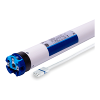
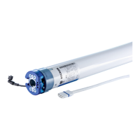
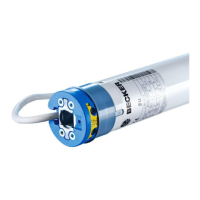
Details the process of attaching the drive unit to the system, including necessary components.

Assembling and disassembling the mounting pin

Explains how to install and remove the drive's mounting pin for secure placement.

Assembling and disassembling the drive adapter

Guides on fitting and removing the drive adapter for torque transmission and safety.

Mounting the drive in the tube

Mounting for profile shafts

Specific instructions for mounting the drive into profile shafts, accounting for groove tolerances.

Mounting for round shafts

Procedure for mounting the drive in round shafts, ensuring proper torque transmission.

Compatible Centronic transmitters

Commissioning with a CentronicPLUS transmitter

CentronicPLUS Transmitter Symbols

Defines symbols used on transmitters and their corresponding functions during commissioning.

CentronicPLUS Operating Modes

Describes the different operational states like Normal mode, Receiver selection, and Setting mode.

Connecting the tubular drive

Establish programming mode

Readying Drive for Programming via Power Cycle

Steps to prepare the drive for programming by cycling the power supply.

Programming the CentronicPLUS transmitter

CentronicPLUS Assignment Status

Details the meaning of LED indicators on the transmitter for assignment status.

Adding additional transmitters to the installation

Selection of the receiver for the setting mode

Receiver Assignment Status

Explains LED indicators for receiver status during selection in setting mode.

Checking the running direction (CentronicPLUS)

Changing direction via drive switch

Instructions on how to reverse the motor's rotation using the physical direction switch.

Changing direction via transmitter

Guidance on adjusting the motor's running direction using a CentronicPLUS transmitter.

Intelligent Installation Management (CentronicPLUS)

Limit Position Status Indicator

Describes the indicator that shows if limit positions have been set for the drive.

Setting Limit Positions (CentronicPLUS)

Lower Point to Upper Point

Procedure for setting both the lower and upper limit positions of the tubular drive.

Lower Point to Upper Stop

Method to set the lower limit and the permanent upper stop for the drive.

Changing Set Limit Positions

Instructions for modifying existing limit positions or extending the travel range.

Deleting Limit Positions (CentronicPLUS)

Deleting Individual Limit Positions

Steps to remove a single set limit position from the drive's memory.

Deleting Both Limit Positions

Procedure for clearing all programmed limit positions from the drive.

Intermediate Positions I + II

Setting/Modifying Intermediate Position

How to define or change specific intermediate stopping points for the drive.

Travelling to Intermediate Position

Instructions on how to move the drive to a pre-set intermediate position.

Deleting Intermediate Position (CentronicPLUS)

Deleting Intermediate Positions

Factory Reset (CentronicPLUS)

Reset via CentronicPLUS Transmitter

Method to reset the drive to factory default settings using an existing transmitter.

Reset via Universal Programming Unit

Procedure for restoring factory settings using a dedicated programming unit.

Commissioning with a Centronic transmitter

Centronic Transmitter Symbols

Defines symbols used on the transmitter for commissioning Centronic systems.

Connecting the Tubular Drive (Centronic)

Steps for electrically connecting the tubular drive to the power supply.

Readying Drive for Programming via Power Cycle (Centronic)

How to prepare the drive for programming by manipulating the power supply.

Checking the running direction (Centronic)

Changing direction via drive switch

Instructions for reversing motor rotation using the drive's built-in switch.

Changing direction via master transmitter

Guidance on setting the correct running direction using the master transmitter.

Intelligent Installation Management (Centronic)

Limit Position Status Indicator

Explains the indicator for un-set limit positions in Centronic systems.

Setting Limit Positions (Centronic)

Lower Point to Upper Point

Procedure to set both lower and upper limit positions using the master transmitter.

Lower Point to Upper Stop

Method to set the lower limit and the permanent upper stop for the drive.

Deleting Limit Positions (Centronic)

Deleting Individual Limit Positions

Steps to remove a single programmed limit position.

Deleting Both Limit Positions

Procedure to clear all programmed limit positions.

Deleting Intermediate Position (Centronic)

Programming Additional Transmitters

Deleting Transmitters

Deleting Individual Transmitters

Instructions for removing specific programmed transmitters from the drive.

Overwriting the Master

Readying Drive for Programming via Power Cycle

Steps to prepare the drive for programming by cycling power.

Readying Drive for Programming via Radio Switch

Procedure to prepare the drive for programming using the radio switch.

Setting Limit Positions with Auto-install

Obstacle Detection

Additional Functions

Fabric Untensioning Function

How to enable or disable the fabric untensioning feature.

Programming Run Times

Instructions on setting specific operational times for the drive's functions.

Deleting Run Times (CentronicPLUS)

Deleting Run Times (Centronic)

Activating/Deactivating Run Times (CentronicPLUS)

Factory Reset (Centronic)

Local Operation with Single Button

Button Commands

Details the functions and sequences triggered by single button presses.

Disposal

Maintenance

Technical Data dia. 35

Technical Data dia. 45

Error Messages

Troubleshooting Guide

Sample Wiring Diagram

Declaration of Conformity

Initial Setup Guide

Add to Installation and Assign Channel

Steps to integrate the drive into the system and assign a communication channel.

Programming in Setting Mode

Procedure for entering and configuring the drive's setting mode.

Setting Limit Positions: Down to Up Stop

Guide to setting the lower limit and the upper stop positions.

Setting Limit Positions: Down to Up

Instructions for setting the lower and upper limit positions.

Deleting Limit Positions

How to remove programmed limit positions from the drive.

Optional Settings: SWC54xx PLUS

Details on optional settings and parameters for the SWC54xx PLUS controller.

Exit Setting Mode

Procedure for safely exiting the drive's setting mode.

Teach-in Sensor

Steps to activate and configure an integrated sensor for the drive.

Related product manuals