64 DeepMind 12 User Manual
8.3.2 OSC 1 PWM FADER
• The OSC 1 PWM fader controls the PULSE WIDTH of the OSC 1 SQUARE
waveform, or the depth of PULSE WIDTH MODULATION (PWM) applied to the
OSC1 SQUARE waveform.
The PWM SOURCE is selected in the OSC EDIT page described later in this
section.
• When the PWM source is set to MANUAL, the fader controls the
PULSE WIDTH.
• When the PWM source is set to any of modulation sources, the fader
controls the depth of PULSE WIDTH MODULATION.
PWM adds harmonic structure to the sound, and is often used to create a
phasing/movement eect, or used when creating string-type sounds and
sonic drones.
The pulse wave (aka rectangle wave) is often described as more "narrow
sounding" than a fully symmetrical square wave. As the pulse width
modulation is increased, the "thinner" or "more hollow" the sound will
become. Very high values of PWM played at very low frequencies will start to
sound like clicks, pops or thumps.
As you increase the PULSE WIDTH, the ratio of the positive cycle to the
negative cycle (also jointly known as duty cycle) will increase. The PULSE
WIDTH MODULATION does not aect the SAWTOOTH waveform.
The OSC 1 PWM range is from 50.0% (symmetrical square-wave) to 99.0%
(short pulsewave). The default OSC 1 PWM setting is 50.0%.
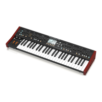
With a PULSE wave, the harmonic content changes depending on the pulse
width. It is characterized by a lack of the nth harmonic series when the pulse
width is 1/n. The example below does not have 3rd, 6th, or 9th harmonics
because the pulse width is 1/3 (33%).
PULSE WIDTH MODULATION
50%
75%
99%
The characteristics of the PULSE waveform are shown below:
The fader position, current value, and stored value for the OSC 1 PWM fader
is shown on the PROG screen. There is also a visualization of the modulation
as shown below.
Note: Whenever two waveforms are shown in the display, the top waveform
represents the summed output of the OSCs, and the bottom waveform
shows the parameter being adjusted.
The summed output shows 4 cycles, while the parameter being adjusted
shows a single cycle, allowing you to see the detail of the changes you are
making while adjusting the parameter.
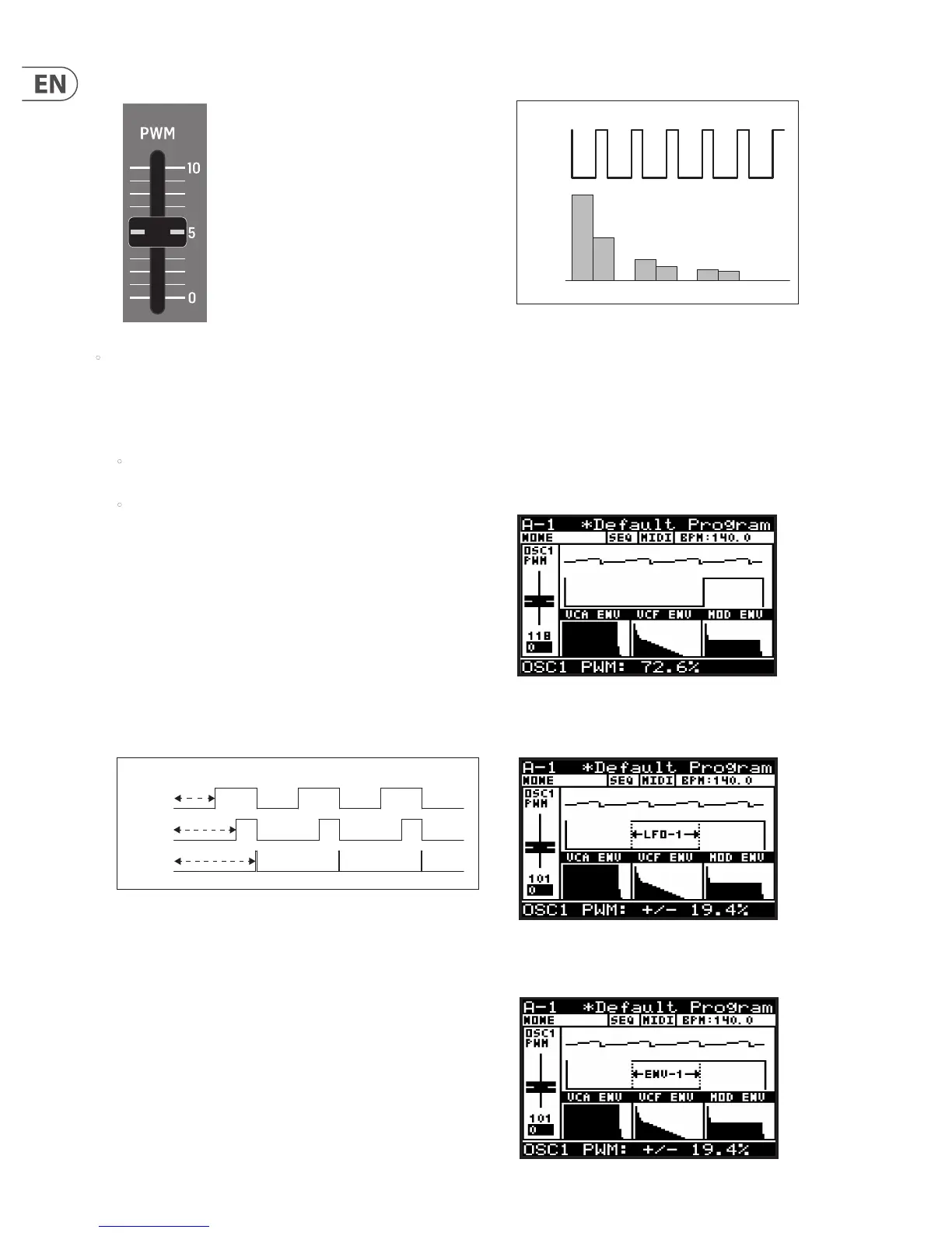
Note: When an LFO is used as a PWM source, the arrows indicate the range
of modulation, as shown below. In this mode, the PWM fader is used to
adjust the amount of modulation from 0 to ± 49%.
Note: When an ENVELOPE is used as a PWM source, the arrows indicate the
range of modulation, as shown below. In this mode the PWM fader is used to
adjust the amount of modulation from 0 to ± 49%.
HARMONIC
CONTENT
f 2nd 7th 8th
PULSE WAVE
OSC
(33% PULSE)
4th 5th