US-EN Installation and operation instructions
DRYPOINT
®
M intelligence 11
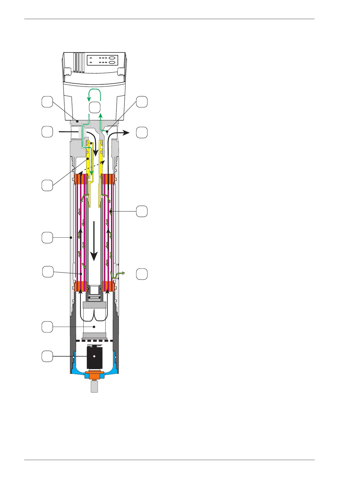
2.3.1. Operating principle
Humid compressed air (2) enters the unit through the
housing head (1) and ows downwards through the core tube
of the membrane element (5). A nanolter is located at the
outlet of the core pipe
(6) xated, which removes residual aerosols and particles
from the compressed air. The resulting condensate is drained
o at the base and is discharged by the oat drain (7).
At the nanolter element, the compressed air is directed in
the opposite direction and the humid compressed air ows
through the membranes of the internal membrane element.
A partial ow (9) of the compressed air
will be branched after the membrane element and bypasses
the sensor continuously in the purge air control. Based on the
sensor signals, the purge air control opens the purge air inlet
to the membrane dryer, if purging is required. As a result, the
purge air pressure drops to the atmospheric pressure and
is much dryer than the compressed air, as the moisture is
distributed to a much larger volume.
The very dry purge air (10) will be routed through the purge
air channel in the head and purge air nozzle (3) to the outside
of the membranes (11) and will be evenly distributed due to
the orderly position of the membranes. This means that there
are two air ows through the membrane element (5) with
dierent humidity content in the counter ow.
Humid compressed air at the inside and dry purge air at the
outside.
Due to the humidity gradient, water diuses from the
compressed air to the purge air. The humid purge air (12) is
then released to the ambient air. The dried compressed air (8)
leaves the membrane dryer.