16 RCM410R-x_D00403_01_M_XXEN/09.2020
Operation and settings on the device
4 Operation and settings on the device
4.1 Control panel RCM410R
Control panel RCM410R-1/-2
4.1.1 STATUS LED
Multicoloured display of various operating modes.
T / R
ton(s)
Ext 10 4
2
1
0,8
0,6
0,40,20
I∆n(A)
Ext 30 10
5
1
0,5
0,3
0,1,03,01
25
%
50
75
%
100
2
AL
1
S2S1
**
A2A2
A1A1
11 14 12
BA-+
A
B
C
D
E
F
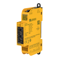
Control panel
A STATUS LED ON – operating modes
B ALARM LEDs – AL1 / AL2
C VALUE DISPLAY LEDs – 25, 50, 75, 100 %
D POTENTIOMETER 1 – Residual operating current I
Δn
E POTENTIOMETER 2 – Response delay t
on
F T/R BUTTON – Test/Reset
ON
Bender
RCM410R
T / R
ton(s)
Ext 10 4
2
1
0,8
0,6
0,40,20
I∆n(A)
Ext 30 10
5
1
0,5
0,3
0,1,03,01
25
%
50
75
%
100
2
AL
1
S2S1
**
A2A2
A1A1
11 14 12
BA-+
LED
Operating mode
GREEN
START PHASE
Device booting after start
NORMAL OPERATION
Device in fault-free state
YELLOW
flashing
CT FAULT
CT connection fault
RED
DEVICE ERROR
Restart or replacement of the device
required.
BLUE
flashing
NFC ACTIVE
(for service purposes only)
 Loading...


