Operation and setup
24
RCMA423-DM_D00064_03_M_XXEN/06.2017
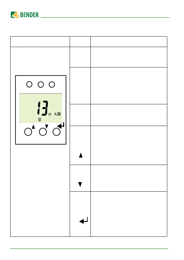
5.2 Function of the operating elements
User interface Element Function
ON,
green
is continuously lit: Power On LED,
flashes: system fault or malfunction
of connection monitoring
AL1,
AL2
LED alarm 1 is lit (yellow):
Response value 1 has been reached
(I
n1
)
LED alarm 2 is lit (yellow): Response
value 2 has been reached
(I
n2
)
13 mA
M
13 mA flow through
the measuring current transformer,
Fault memory active
T,
Test button (> 1.5 s):
Indicating display elements availa-
ble for this device, starting a self
test;
Arrow-up button (< 1.5 s):
Menu items/values
R,
Reset button (> 1.5 s):
Erasing the fault memory;
Arrow-down button (< 1.5 s):
Menu items/values
MENU,
MENU button (> 1.5 s):
Starting the menu mode;
Enter button (< 1.5 s):
Confirming menu item, submenu
item and value.
Enter button (> 1.5 s):
Back to the next higher menu level.