Operation and setting
24
VME420_D00026_03_M_XXDE/04.2019
5.2 Function of the operating elements
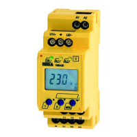
Device front
Ele-
ment
Function
ON
Power On LED, green
AL1,
AL2
Menu item LEd deactivated:
LED Alarm 1 lights (yellow):
Response value > U reached
LED Alarm 2 lights (yellow): Res-
ponse value < U reached
AL1
and
AL2
Menu item LEd deactivated:
Both LEDs light when the fre-
quency response values > Hz or <
Hz are reached.
AL1,
AL2
Menu item LEd activated:
LED Alarm 1 lights (yellow):
K1 signals an arbitrary alarm
LED Alarm 2 lights (yellow):
K2 signals an arbitrary alarm
225 V,
M
Display in standard mode: U
n
=
225 V;
Fault memory active
T,
Test button (> 1.5 s):
Indication of the useable display
elements, starting a self test;
Up key (< 1.5 s):
Menu items/values
R,
Reset button (> 1.5 s):
Deleting the fault memory;
Down key (< 1.5 s):
Menu items/values