Do you have a question about the Bentel Security FireClass 100 and is the answer not in the manual?
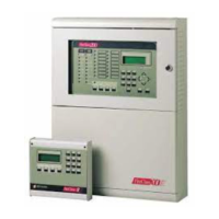
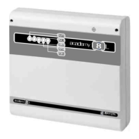
Defines the function of the FireClass100 control panel in managing the fire prevention system.
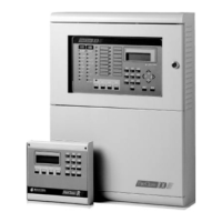
Describes repeaters as small panels for remote control and displaying system messages and buzzer signals.
Details the various LED indicators on the control panel and their meanings for different statuses like ALARM, FAULT, and power.
Mentions the back-lit display used for showing status messages and information.
Describes the built-in buzzer that signals panel status through acoustic signals.
Explains the different acoustic signals the panel buzzer uses to indicate status like PREALARM, ALARM, and FAULT.
Describes how the panel display shows STANDBY, WARNING, PREALARM, ALARM, and FAULT statuses with specific messages.
Describes the conditions when the control panel is in standby mode, including LED and display indications.
Explains how faults are signalled through LEDs, messages, acoustic signals, and output points.
Details the information displayed for first, last, and total faults, including identifiers and device types.
Explains how to use the SILENCE button to put silenceable FAULT Outputs into standby status and silence buzzers.
Describes the WARNING status, indicating a point has exceeded the warning threshold and may go into ALARM.
Explains the PREALARM status, where a point exceeds the alarm threshold but requires a programmed time to enter ALARM.
Describes the ALARM status, signalling the activation of output points due to an input point entering ALARM.
Details the information displayed for first, last, and total alarms, including identifiers and device types.
Explains how input and output points can be associated with 16 software zones, affecting ALARM status.
Describes the PAS feature, where a software zone enters ALARM status after a fixed or PAS delay ends.
Explains how the SILENCE button forces output points into standby and its behaviour in DAY and NIGHT modes.
Details the RESET command to stop ALARM, Prealarm, Warning, and FAULT conditions, requiring authorization.
Describes the TEST button's function to activate all control panel LEDs, buzzers, and repeater buzzers.
Explains the two operating modes, DAY and NIGHT, affecting SILENCE behaviour and alarm thresholds.
Describes how the FireClass100 automatically varies alarm thresholds, especially in DAY Mode, to adjust sensitivity.
Explains Drift Compensation for analogue sensors, its purpose in precise analysis, and fault detection.
Details how the control panel can be programmed to request maintenance, signalled by FAULT status on a specific date.
Explains the DISABLE option to disable/enable devices, zones, and bell outputs, affecting status signalling.
Describes the Alarm Verify function to check the veracity of an ALARM status, using verify time and counter.
Explains that the FireClass100 logger records the data of the last 200 events for review.
Details how outputs can be programmed for extinction methods, with programmed delays for activation.
Explains how to access the Modifying menu to disable devices, clear counters, and modify telecom parameters.
Details the process of entering the user code to access the Modifying menu, including the default code.
Explains the effect of disabling monitoring devices, preventing ALARM or FAULT status generation.
Describes how disabling control devices prevents them from activating during ALARM or FAULT status.
States that enabled/disabled modes for Bell Outputs are similar to Control Devices.
Explains how disabling/enabling a software zone affects all its associated devices.
Discusses disabled repeaters, their inability to command the panel, and lack of FAULT status generation when lost.
Outlines the step-by-step procedure to disable control panel items like Loop Devices, Bell Outputs, Software Zones, and Network Devices.
Explains how to enable or disable the conventional line by positioning the cursor and pressing a key.
Describes the error message displayed if an invalid address is entered for device configuration.
Explains how to use the 'Delete Verify' option to clear the Verify Counter of each detector.
Describes using the 'Delete logger' option to clear the contents of the event logger.
Explains how to change programmed telephone numbers for the Telecom Module.
Details how to record, listen to, or change messages for the Telecom Module.
Describes enabling or disabling Teleservice (ON/OFF) for the Telecom Module.
Explains how to view parameters for devices on the loop, software zones, bell outputs, and network devices.
Describes viewing parameters of the system options via the Options menu.
Details how to view the control panel version number and compliance details.
Explains how to select the Logger option to view the most recent event and scroll through stored events.
Lists the data fields stored in the logger: Event Type, Event Number, Panel, Origin, Hour/Date, and Address.
Explains how to use the Print option to print all logger contents on a connected printer.
| Brand | Bentel Security |
|---|---|
| Model | FireClass 100 |
| Category | Control Panel |
| Language | English |