15
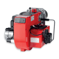
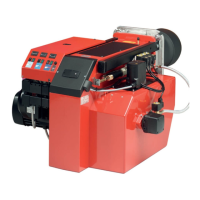
Bentone B55/B65
General
d
2
d
1
d
3
E
Return line
Suction line
3.7 Burner installation
3.7.1 Hole pattern
Check that the hole pattern on the boiler matches the pattern on the burner
flange.
Flame head d
1
d
2
d
3
B55 (160)* 165 M12 (226)* 254-295
B65 (160)* 210 M12 (226)* 254-295
The hole pattern can be reduced if the burner pipe is fitted from the front and
the heels in the flange are ground off.
3.8 Installing the burner
1. Separate the burner body and the flange.
2. Fit the flange and gasket on the boiler.
3. Insulate between the burner pipe and boiler door to reduce heat
radiation.
4. Slide the burner body on to the guides.
5. Pull the brake plate off the oil pipe.
6. Fit the chosen nozzles (see Technical data).
7. Fit the brake plate and check the ignition electrodes (see Servicing the
burner).
8. Slide the burner together and secure it with the nuts (E).
3.9 Oil lines
1. Check the size of the oil line (see Pump instructions)
2. An oil filer (1/2”) must be fitted to the oil line. If an air trap is fitted then
the oil filter should be fitted to the oil line before the air trap.
3. With a single pipe system the return plug must be removed (see Pump
instructions).
4. When fitting oil hoses, check that the supply and return hoses are
connected to the right couplings on the oil pump. The hoses must be
positioned so that they are not subjected to tensile stress or sharp
bending.
5. Bleed the oil system. The oil pump will be damaged if it is run dry.
6. The vacuum in the suction line should not exceed 0.3 bar during
commissioning.
3.10 Electrical connections
1. Turn off the main power switch.
2. Connect the Eurostecker connectors (see Electrical equipment).
3. Check that the burner control switch (S1) is off.
4. Fit the Eurostecker connectors on the burner.
5. Turn on the main power switch.
6. Check the direction of rotation of the burner motor.